Phase Contrast Illumination |
|
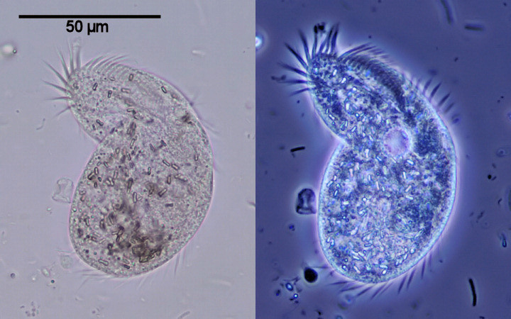
| Ciliate (Oxytricha saprobia?) in brightfield (left) and with phase contrast illumination (right) |
| Gregor T. Overney, California, USA |
|
|
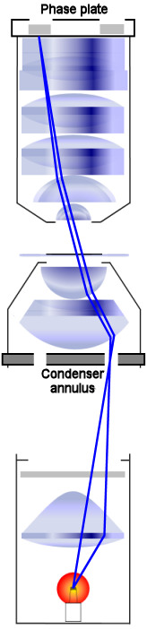
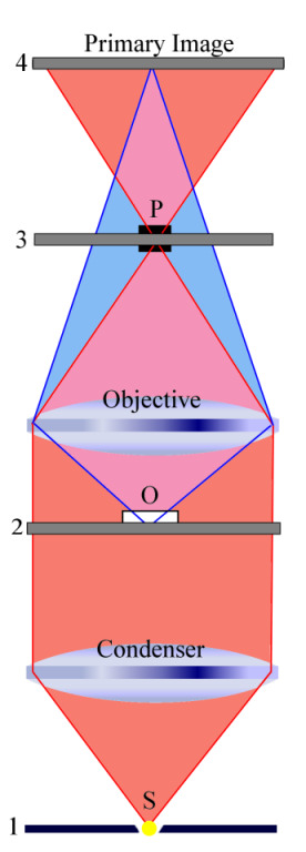
The topic of phase contrast microscopy is well explained in good textbooks and on many websites (such as [1]). The purpose of this paper is not to write another introduction to phase contrast illumination. This article shall merely be about some of my experiences I collected using this interesting type of illumination. Phase contrast microscopy was invented in 1934 by Dutch physicist Frits (Frederik) Zernike (1888 - 1966). The main aspect of this invention is to convert phase differences into amplitude variations that can easily be detected. For instance, phase contrast (PC) microscopy can be used to produce high-contrast images of transparent specimens, such as living epithelial cells. It is an interference technique that requires at least partially coherent light to illuminate the specimen (more precisely, partial, longitudinal coherence is required to make PC work). The numerical aperture (NA) of the condenser is reduced by the geometrical arrangement of the annular ring. However, this reduction in the condenser's NA does in no way diminish the benefit of phase contrast illumination for transparent specimens that mainly change the phase of the diffracted light beam rather than its amplitude. |
|
|
I compared brightfield (BF), BF with a green interference filter, circular oblique lighting (COL) ([2]), darkfield (DF) ([3]), DF with a blue filter, and phase contrast without green interference filter using images taken from Stauroneis phoenicenteron. I used a Plan Achromat 40x objective with NA 0.65 for all DF work. I used a Plan Fluor 40x objective with NA 0.75 for BF and COL and a DL Plan Achromat 40x objective with NA 0.65 for phase contrast. The results are depicted in the figure below. When taking these photomicrographs, I carefully focused on just one row of dots located towards the middle of this diatom.
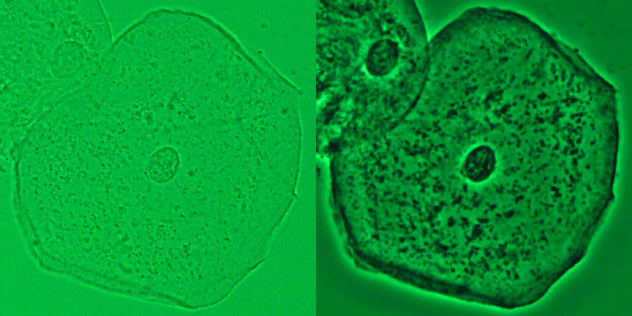
From the above data, it is perfectly obvious that the use of phase contrast illumination is rather pointless for looking at specimens that offer sufficient contrast in brightfield when trying to maximize contrast as well as resolution. While DF and COL offer at least the same resolution, phase contrast limits the resolution due to the condenser annulus. However, this changes dramatically if the specimen is flat and appears rather transparent in brightfield. While DF and COL often offer enough contrast, BF is not of much help. The picture below shows an epithelial cell in BF using a Plan Fluor 40x lens (NA 0.75) (left) and with phase contrast using a DL Plan Achromat 40x (NA 0.65) (right). A green interference filter is used for both images.
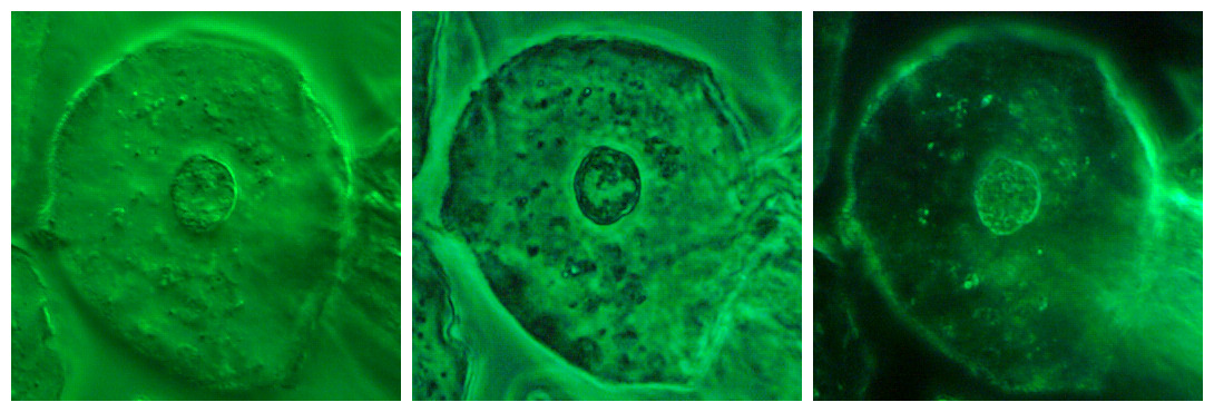
When using COL and DF, much more contrast can be obtained as can be seen in the picture below. The first image shows an epithelial cell in COL using a Plan Fluor 40x objective (NA 0.75); the second one shows the same cell with phase contrast illumination using a DL Plan Achromat 40x (NA 0.65); and the third image shows again the same cell in DF using a DL Plan Achromat 40x (NA 0.65). A green interference filter is used for all cases.
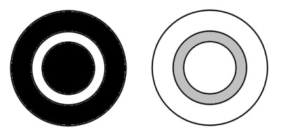
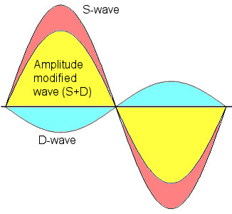
Phase contrast is most ideal for this application of thin, transparent samples such as epithelial cells. - When looking at the pictures above, some of the cellular features appear dark in front of a brighter background when observed in PC. This is usually the case when the S-wave is phase shifted by +90° (known as positive phase contrast). Essentially, objects with a higher refractive index than the surrounding medium appear dark (assuming, of course, the same thickness). - Lipid droplets and vacuoles in plant cells and protozoa usually appear brighter in the surrounding cytoplasm when observed with positive phase contrast. When looking at the images in phase contrast depicted above, we can also easily find certain image artifacts due to the effects of halo and shade-off. Halos occur because the ring in the phase plate ("located" in the back focal plane of the objective) also receives some diffracted light from the specimen. To alleviate this problem, the phase plate annulus (or its image) is wider than the condenser annulus when both are observed with a phase centering telescope. Shade-off, another optical effect, is more obvious in extended phase objects. Phase contrast illumination is recommended by many microscopists for the study of protists (for instance, see [4]). - Many interesting articles have been published in the Micscape Magazine about this contrast method (for example, see [5-10]). |
|
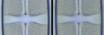
In the last paragraph, we look at the performance of a phase contrast objective for use in brightfield illumination. Many amateur microscopists find themselves in a financial dilemma. Shall they purchase both, a dedicated phase contrast objective and a general purpose objective for brightfield (as well as COL and DF) or can a phase contrast lens reasonably well be used as general purpose objective lens? Let us focus on positive phase contrast. As mentioned above, the phase plate reduces the amplitude of the S-wave (non-diffracted wave) by a significant amount. The stronger this reduction, the more contrast one obtains with PC illumination. However, the stronger this reduction, the more is also the image softened in brightfield. Interesting, the manufactures have recognized this limitation and developed phase contrast lenses with phase plates that do no longer reduce the amplitude this significantly. Unfortunately, this is just a compromise that reduces contrast with PC while making these lenses more suitable for brightfield. Most makers of Plan Fluor lenses have followed this example to lower the contrast of phase contrast while allowing the user to use his lens for better quality work in brightfield or fluorescence microscopy. If the goal is to maximize contrast with phase contrast illumination, a dedicated phase contrast lens should be purchased. The following is a comparison between a "high contrast" Plan Achromat 40x phase contrast lens and a Plan Achromat 40x lens. As we can see from the image below, there is no difference in resolution.
This summarizes the results when looking at diatom frustules. Even a "high contrast" Plan Achromat phase contrast lens is perfectly suitable for this kind of work in brightfield. - But when looking at stained histology sections, the phase contrast lens does not perform as well as its brightfield sibling. The images below show a stained histology section observed with the same two lenses and photographed with a digital camera using a CMOS image sensor. This image sensor is not too suitable in discerning small changes in contrast. While the difference is significant when observed through the eyepieces, the digital camera's limitation in recording contrast features shows only a small change.
|
|
I want to thank Dr. Fei Liu for many suggestions and stimulating discussions. The technical support of C&N for designing the HTML version of this article is greatly acknowledged. Last but not least, I thank all anonymous supporters who provided assistance and equipment. |
|
Comments to the author, Gregor Overney, are welcomed.
Please report any Web problems or
offer general comments to the
Micscape
Editor,
via the contact on current Micscape Index.
Micscape is the on-line monthly magazine
of the Microscopy UK web
site at http://www.microscopy-uk.org.uk.