Why I Like Darkfield Illumination

Aulacodiscus kittonii with COL (left) and with DF illumination (right)
Gregor T. Overney, Sunnyvale, California, USA

Introduction

We have seen the wonderful images people are able to record with phase contrast illumination (PC) [1], circular oblique lighting (COL) [2], brightfield illumination (BF), and differential interference contrast (DIC) microscopy [3]. And most certainly, most of us have already enjoyed the wonderful results darkfield illumination (DF) is able to show [4]. (For a small tutorial about DF, please look at [5].)

I am not going to debate which of these illumination techniques offers the best balance between resolution and contrast. All these methods provide excellent results when applied professionally for a suitable task. But I want to share some of my personal experience with DF and emphasize the point that DF should be one of the available choices for any serious amateur microscopist. If you do not have a DF setup and are interested in getting one, please read Ted's good article [6].

Advantages of DF

I often promote DF because of the following points:

  1. Unlike PC, DF does not "suffer" under the restriction of the numerical aperture of the condenser due to an annular ring. DF can offer better resolution than PC.
  2. DF can offer higher contrast than COL for many applications. I will show one example that demonstrates this.
  3. DF exists already for many decades and matured into a well-understood and approved illumination technique.
  4. DF can be implemented rather inexpensively by putting an appropriately sized opaque disk into the light path located close to the condenser's diaphragm. (See [5] and [6] for more information.)
  5. By using an objective with suitable numerical aperture, we can easily turn DF into COL. The amount of the DF contribution can then be adjusted with the help of the condenser's aperture. (See [2] and references therein for a detailed description.)

In the following comparison, I intentionally skip PC and DIC. PC is often not recommended for most applications in amateur microscopy. It is a rather expensive method. (A used PC setup for a Leitz Ortholux costs around US$800 and a new PC setup for the Nikon E200 is around US$1,500.) PC is used in biology to study unstained cellular structures, which are very thin specimens. Unfortunately, it is rather common that amateur microscopists look with PC at less suitable specimens and greatly amplify the occurrence of halos around structures. (ADL (apodized phase contrast dark-light) objectives, which are designed by Nikon for its inverted microscopes, can reduce this disturbing halo effect for special cases.) - DIC is very expensive and therefore not a feasible addition for an amateur microscope setup. DIC is also not without problems, but DIC makes use of the full resolution capabilities of objective and condenser.

Equipment for DF Evaluation

Let me illustrate the power of DF with a simple example that can easily be reproduced with any reasonable amateur microscope setup. The following are the required components:

  1. A scope with a decent illumination. I strongly recommend Köhler illumination with at least a 20-Watt halogen bulb.
  2. An achromat 40x objective with a numerical aperture (NA) of at least 0.65. I also use a Nikon Fluor 40x objective (semi-apochromat) with an NA of 0.75.
  3. A low-cost Abbe condenser with an NA of at least 0.7 (when used without immersion oil). I measured that my Nikon Abbe condenser offers at least an NA of 0.75 when used dry. It's a low-cost Abbe 1.25 oil condenser that allows a slider to be moved into the condenser.
  4. A darkfield stop (also called central opaque 'patch stop') for the condenser mentioned under point "3". (See Figure 1 for an image of a Nikon Abbe slider condenser.)
  5. A test specimen that has a structure that presents an acceptable challenge for the above setup. I decided to take one of Klaus Kemp's excellent diatom test slides. (See [7] for more information about diatom test slides.)

Figure 1 - The Nikon Abbe slider condenser NA 1.25 oil. The darkfield slider is also depicted.

Using the test slide mentioned under point "5", I selected the diatom Stauroneis phoenicenteron. This diatom has a frustule spacing (spacing between the dotted lines) of approximately 0.72 micrometers (µm). Why is this a challenge for a 40x objective with an NA of 0.65? The smallest, resolvable separation d is given by (λ is wavelength of light)

d[µm] = 0.61 λ[µm] / NAObjective

Using a wavelength of 0.546 µm (green light) and a NA of 0.65, we obtain for the smallest, resolvable distance d, also called resolving power of a microscope, a value of 0.512 µm. This value is smaller than the frustule spacing of 0.72 µm and hence we should be able to resolve this structure. (Of course, the above equation is only correct when the numerical aperture of the condenser is larger than or at least equal to the NA of the objective.)

(Side note: Pleurosigma angulatum, which is also available on Klaus Kemp's test slide, has a frustule spacing of just 0.525 µm and would present a far better challenge for DF and COL. Unfortunately, I was not able to resolve enough features for digital recording with BF due to serious lack of contrast. But DF and COL are able to resolve Pleurosigma angulatum with a 40x achromat objective.)

Comparison of Various Illumination Techniques

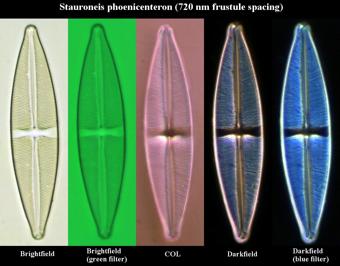
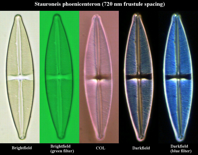
I compared BF, BF with a green interference filter, COL, DF, and DF with a blue filter using images taken from Stauroneis phoenicenteron. I used an achromat 40x objective with NA 0.65 for all DF work to ensure that my simple darkfield stop in my Abbe slider condenser offers optimal DF. I used a semi-apochromat 40x objective with NA 0.75 for BF and COL. Since the Abbe condenser offers an NA of around 0.75 when used dry, my setup for COL does not contain much light from the so-called DF component, which is light that is only captured by the objective when diffracted in the specimen plane. The results are depicted in Figure 2. When taking these photomicrographs, I carefully focused on just one row of dots located towards the middle of this diatom.

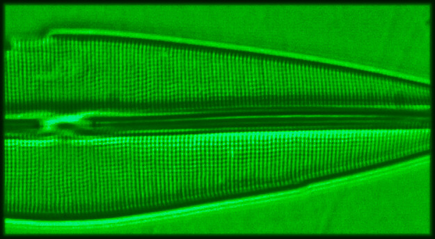
Figure 2 - Diatom Stauroneis phoenicenteron. For the first three images, I used a semi-apochromat 40x objective with an NA of 0.75. For the last two images (darkfield images), I used an achromat 40x objective with an NA of just 0.65. The images were recorded with a digital camera using a CMOS image sensor. (Click on image for larger version.)

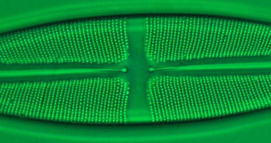
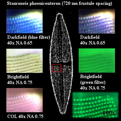
In a second step, I cropped the row I selected for focusing, including some neighboring rows, out of each of the five individual images and enlarged the cropped sections by a factor of two for better 
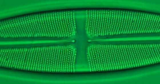
visibility. I summarized the results in Figure 3. For reference, I also added a higher resolution image that I obtained with an achromat 100x objective with NA 1.25 using BF (see lower right image in Figure 3). Of course, I used immersion oil for this reference image. Figure 4 shows 
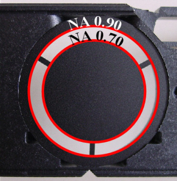
Stauroneis phoenicenteron observed with an achromat oil immersion 100x objective and an achromat condenser with NA 0.90 using BF. For Figure 4, I did not use immersion oil between the achromat condenser and the slide. Of course, Figure 4 does not show a real high-resolution image of this diatom. Using a special darkfield oil immersion condenser, finer detail could be revealed.

Figure 3 - Five of these image sections are taken from the images of Figure 2. The inset depicts a diatom with a red square surrounding the area that has been cropped out. The image, which is located towards the bottom right, shows the same section of this diatom recorded with an achromat 100x oil immersion objective with an NA of 1.25.

Figure 4 - For this image of Stauroneis phoenicenteron I used an achromat 100x oil immersion objective with an NA of 1.25 together with an achromat condenser with an NA of 0.90/dry using BF. A green interference filter was used. (Click on image for larger version.)

I was using a PixeLink PL-A662 FireWire digital camera. This device offers great flexibility to control the imaging process and connects directly to a C-mount adapter connected to a trinocular viewing body. When looking at these images of Figure 3 that were obtained with DF, we can easily see very bright sections indicating intensities that were not adequately captured by the digital imaging device (see upper right corners of the two topmost images in Figure 3). This has nothing to do with DF but is due to a limitation of the 10-bit sampling used by the digital imaging device. Today, most digital imaging sensors perform the analog to digital (A/D) conversion at a 12-bit or even 14-bit sampling rate.

DF is indeed a very powerful method to study the fine structure of diatoms. DF illumination is easy to setup and, a little to my surprise, I recognized more detail in this particular structure using DF together with the cheaper 40x objective than I was able to see with BF or COL using the much more expensive semi-apochromat.

Sub-resolution Particles

Of course, DF is not only useful for diatom shells. It is the method of choice for investigation of subresolution particles. A subresolution particle is a particle with a size smaller than the minimal resolvable particle size. We learn from diffraction theory that the minimal particle size diameter that any compound microscope with Köhler illumination can resolve in green light (0.546 µm) is just about 0.5 µm. (2d = 1.22 × 0.546 / 1.40 = 0.48 µm.) In this case, any subresolution particle will appear in the image like a particle with a diameter of around 0.5 µm; see Figure 5.

Figure 5 - When the size of a particle falls below the minimal particle size that can be resolved with a given optical setup (diameter = 2d), the size of the image of the particle is no longer smaller than the minimal particle size, but its contribution to the image contrast decreases as the diameter of the subresolution particle gets smaller.

Whether or not we are able to detect a subresolution particle will depend on our image sensor's capability to register its influence on the overall contrast of the image. For instance, in BF of unstained samples, the contrast change due to subresolution particles is often too weak to be recordable, and hence these subresolution particles remain invisible. It is not uncommon that DF is capable of providing enough contrast to make many subresolution particles detectable (or visible in the recorded image). - An application that requires good contrast and great resolution is the study of unstained bacteria in Amoeba proteus. One other important application for DF is the study of Borrelia duttoni in blood samples (see African relapsing fever).

Certainly, DF is no replacement for BF. And COL shows its strength when used at highest resolutions (NA larger than 1.30). But for many applications that require high contrast, such as diatom shells, DF is highly recommended.

"Light Staining" in DF

If you like to experiment with "light staining" of your specimens, you could also use a simple trick with DF illumination. With Köhler illumination, the field diaphragm is focused into the specimen plane by the condenser. (We also say that the field diaphragm is located in a conjugated image plane.) When using a low-cost Abbe condenser, color fringes will form around the image of the field diaphragm. By closing the field diaphragm more than necessary, we sometimes color the imaged specimens in DF with beautiful colors. As an example of "light staining" in DF, I photographed two pollen grains (see Figure 6).

Figure 6 - Two different pollen grains in DF using a 40x achromat objective with NA 0.65. The pollen grain on the left side is from pumpkin (cucurbitaceae) showing prickly processes. The pollen grain on the right side is from pine (pinus) showing air chambers. (Click on image for larger version.)

A Look at COL

I want to conclude this short article with an interesting experiment I did with COL (not DF). After all, I prefer to use COL whenever DF can no longer provide enough resolution but when additional contrast is required to enhance details. (DF limits the light gathering capability of the objective due to its requirement that no direct light is allowed to enter the objective. BTW, for up to a numerical aperture of around 1.25, Ted Clarke was able to use a darkfield stop together with a LOMO condenser NA 1.40 oil [8].) Again, I did not use any special darkfield condenser, such as the Leitz Cardioid oil immersion darkfield condenser, but the same low-cost Abbe condenser with the darkfield slider I just used for the work shown in the above paragraphs. But this time, I ensured that the condenser is oiled to the underside of the slide. Due to the design of this darkfield slider, the maximum achievable NA of the condenser is according to Nikon's technical specification just about 0.90 (even with immersion oil between slide and condenser). I measured an NA of 0.95. See Figure 7 for an image of the darkfield stop. (Without the darkfield slider, this condenser offers an NA of 1.25.)

Figure 7 - The two concentric, red circles indicate the inner and outer limit of the light cylinder entering the condenser, which projects this incident light into a light cone with an outer cone at NA 0.9 and with an inner cone at NA 0.7.

By taking an achromat 100x oil immersion objective with NA 1.25, I looked at Frustulia rhomboides. The frustule spacing of this diatom is just about 0.30 µm and the frustule structures cannot be detected with a BF setup. Since the darkfield stop creates a light cone between NA 0.7 to 0.9(5) and since the objective can capture light up to NA 1.25, we have an illumination type that could be described as "restricted" COL. The equation to calculate the limit of resolving power for this setup is given by

d[µm] = 1.22 λ[µm] / (NACondenser + NAObjective)

For a wavelength of 0.546 µm (green light), we obtain d = 0.30 µm, which is just enough to resolve the frustules of Frustulia rhomboides. It is amazing to see the result in Figure 8 when using a green filter. I can even see individual dots!

Figure 8 - Frustulia rhomboides using COL with a darkfield slider condenser with an NA of just 0.95 (measured value) and an achromat oil immersion 100x objective with an NA of 1.25. Type-A immersion oil is used between condenser and slide as well as between slide and objective.

Acknowledgements

I want to thank Dr. Fei Liu for many suggestions and stimulating discussions. The technical support of C&N for designing the HTML version of this article is greatly acknowledged. Last but not least, I thank all anonymous supporters who provided assistance and equipment.

References

[1] Protozoa Portraits - Amoeba, Paramecium, Colpidium, Micscape Magazine article by James Evarts, May 1999.
[2] Circular Oblique Lighting (COL), Micscape Magazine article by Paul James, December 2002.
[3] Differential interference contrast image of a Ruffe (Acerina acerina ) photographed by Heiti Paves, Micscape Magazine, May 1997.
[4] Diatoms in Dark-Field, Micscape Magazine article by Roland Mortimer, February 2000.
[5] Molecular Expressions, Optical Microscopy Primer, Darkfield Illumination.
[6] Nature Center Microscope with Darkfield Capability, Micscape Magazine article by Ted Clarke, March 2003.
[7] Klaus D. Kemp, Microlife Services, Somerset, England.
[8] Ted Clarke's website at http://www.couger.com/microscope/Ted-Clarke/.

Comments to the author, Gregor Overney, are welcomed.


Microscopy UK Front Page
Micscape Magazine
Article Library


© Gregor Overney

Published in the March 2004 edition of Micscape Magazine.

Please report any Web problems or offer general comments to the Micscape Editor,
via the contact on current Micscape Index.

Micscape is the on-line monthly magazine of the Microscopy UK web
site at http://www.microscopy-uk.org.uk.