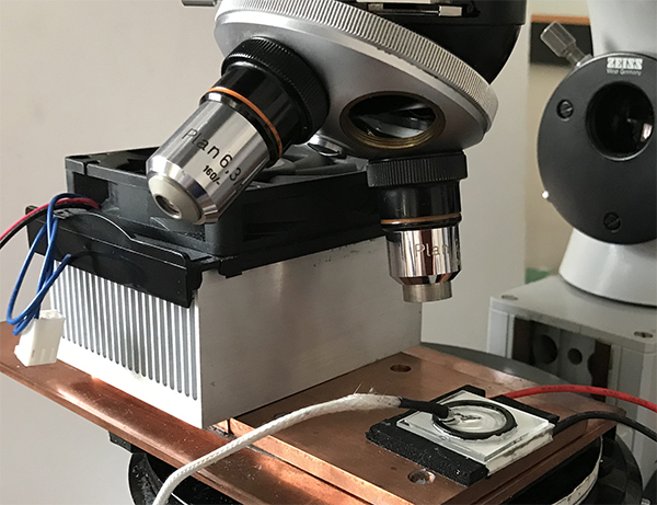
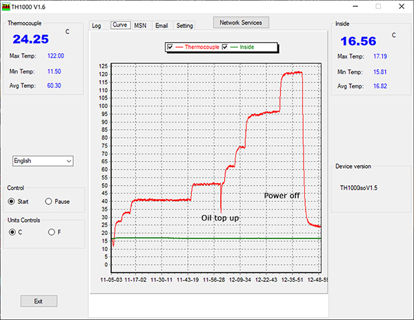
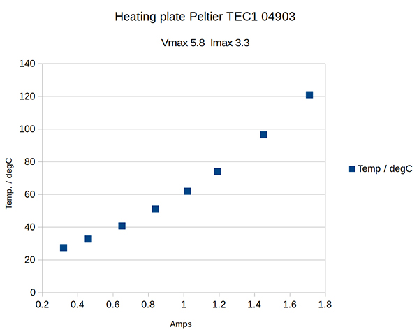
TES1 04903, 5.8V, 3A annular plate
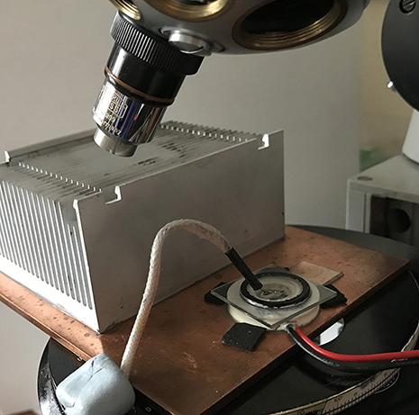
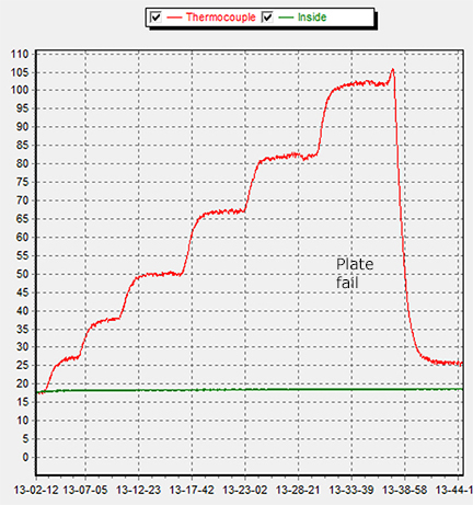
The setup shown below was used and was the design finally adopted for earlier transmitted studies with a hole drilled in the copper plate below the plate hole. A fan was not needed for either this setup or the one above to keep the heatsink at room temp. as there was little if any cooling detected. Good control of the temperature was achieved with rapid equilibrium. Until the current was increased a small step to go just beyond 100°C; this time the plate irreparably failed as shown by the rapid heat loss. This was the only example possessed so have had to order another from China, the only source have found to date.
Comments on trials to date
It is not clear from the limited trials to date whether the TEC1 plate is stable at 120°C or was just lucky that it did not fail. On the EVERREDtronics website the TES1 range are stated to have a higher density of smaller elements so maybe this is a factor. Have also noticed a footnote on this site which states that 100°C is the maximum recommended plate temp. for most models which if the case suggest little room for any leeway on the TES1 model used.
Although commercial Peltier cooling / heating stages are presumably reversing the polarity to select the mode, it may be prudent for homebrew trials to retain the plate polarity but place the hot side uppermost for a heating setup. I was hoping to have a dual cooling / heating setup by just polarity reversal to avoid cleaning off the thermal paste and reversing. When the above two plates were used in cooling mode and correct polarity, Vmax and Imax correlated well. When these plates were used as above for heating, although nearing their Vmax, the current was barely half Imax, suggesting with reversed polarity the junctions were not behaving in the same way (possibly stressed?).
The aim of these trials was to have a setup to gently heat aqueous solutions to encourage crystallisation and study in real time under crossed polars. The same speeding up may also be achieved by adopting slightly concentrated solutions and then chilling. For me, the latter seems the safer route for plates owned and the one will adopt in future. If pursuing heating trials, unless have firm data for a given model for their max. operating temp would advise to keep the max. temp quite modest say 75°C although this should be more than enough to speed crystallisation.
There is an argument that cooling is a better approach to force crystallisation as the crystals will be surrounded by solution. Forced evaporation may form crystals surrounded by an aqueous/air interface which can give unwanted artifacts under the microscope.
The EVERREDtronics site list Peltier modules designed to go to 200°C but no annular models were listed which are the best for transmitted studies.
Comments to the author David Walker are welcomed.
Acknowledgments
Thank you to Michael Wolfson for stimulating email discussions on cooling and heating microscope stages.