A Precision Solution for Digital interfacing a Vivitar 8000 series Camera to Standard Microscope stands and 27.8 / 23.2 oculars made from General Gardening implements.By David Christmass |
Introduction. |
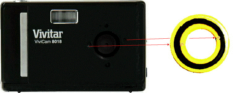
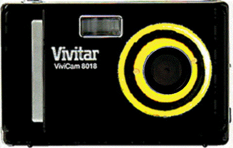
This project began two years ago, after reading an article about connecting a Logitech™ Web cam to a microscope, on Micscape. I have several persistent incapabilities in the arena of computing. First, I can't use a computer unless it has an Apple badge, and runs the traditional Apple Mac Operating System. Second, like, I guess, many, that are interested in microscopes, and who are reading this article, I suffer from extreme bouts of Coulrophobia (fear of Clowns turning up with some kind of upgrade that requires a new operating system), aggravated by (Adobephobia, the frustration to find that Adobe pdf file formats have deviated from their own original standards and won't open unless they are created without multimedia.) Adobephobia is more common among archivists and librarians than any other working cohorts when they do Google searches with a -*.pdf suffix to cut out seven times of nonsense from appearing is search results, or when they find their archive files don't open because Adobe altered the original PDF standard. But it is Disposophobia: (fear of the objects not being found due to stalls and confusions) that is more common among readers of web pages dependant upon Java scripting technology. Sometimes, these phobias, especially Magnophopia, (fear of anything associated to Java™, Sun Microsystems™, or java scripting™ and object orientated programming), can be life threatening, as they leave me hunting my Jugular in complete contemplation of that Vapid Void of Vacancies that appear with errors before my eyes, and especially when presented with even the hint of demands to change my existing learned capacities, or browser technologies, which ostensibly continue to work well if left alone. So after reading, with interest, the article about connecting a Logitech™ camera to a microscope, I became inspired to do likewise: I was sure of success: after all, what could go wrong? Logitech™ originated from Connectix™, Connectix™ developed for Mac OS, and yes there did appear to exist old Connectix™ drivers that promise to run on the Mac OS Classic. I could interface a camera from resources from my old junk driver archives. So I off I trotted, and bought a Quickcam™. Imagine, my horror to find, YOU CAN HAVE ANY DRIVER AS LONG AS IT'S NOT FOR MAC OS CLASSIC, on a 1.3 Mpx Camera. I knew this was not true. I knew the Web camera range of the 1990's before Logitech™ bought Connectix™: so why the Federal obstruction? Well, after trying 3 cameras in the range, I called things a real Christ m arse Day. The problem, as it became apparent to me, was that Logitech™ Cameras used to be made by Philips™, but when manufacturing transferred to China, Philips™ made the software Product ID number completely incompatible to the new camera range: ode for the joy of the jesters! It was then, after 3 weeks of messing about, that I had my first bout of stress, and was declared formally, a Complete and utter Coulrophobe! This was devastating news. I had done my time at University, read my English cannons, contemplated my CPC exams, sat my dinners in Macdonald's™ in Grays in Road, planned my routes to the Bar: I was all set up for a successful bout on the Jury Practice, only to discover my morbid fear of the Circus: all notions of a career as a Justice of the Peace, gone: I was shattered. I contemplated retraining, I contemplated the forthcoming Olympics, maybe I could make something of myself as a competitive cyclist, then I thought of the circuit, the training, and that just reminded me of Clowns on disproportionate cycles: I had a panic attack, all the deep breathing exercises, the calming techniques, failed and faltered and I was just left with that overwhelming desire to have another cigarette and relax. I was the lucky one, for me there was an expert therapist working in our local branch of Wallmart™: As I grew to contemplating my Camera woes while out for a stroll around the Asda™ stores, (that's Camera photography woes not Campaign for real ale woes) a very kind fellow introduced me to a Vivitar™ Camera, called a Vivicam™ 8018. And then, very swiftly, all my problems seemed resolved: the Clowns had gone away, and when I got home, the Camera just turned up on the desktop as a disk unit, and I could transfer my pictures to my computer: oh the relief, I almost felt like giving up smoking altogether, but this was only the first steps along that long and well travelled path to achieve picture graphical interfacing to standards to Mac OS. I was extremely pleased with the product, and the better resolution of the camera was a real bonus to me. I learn now, that similar cameras in the range extend to 12 Mpx and perhaps even more. So my first tentative steps at photo microscopy comprised of placing the flat lens of the camera against the ocular. Using a 15 X Huygens ocular is most problematic, as even the smallest shake of the hand caused blurring or alignment offsets. The biggest problem with this method is the limited field of view apparent on the photograph. One day, when I was doing this, the front plate of the Vivicam™ literally fell off in my hands. What I discovered under the front plate were four mounting holes: the front plate had simply rested in its place within these holes: hey, I thought, I am well blessed, my sins are diminished, maybe Vivitar™ make a mounting accessory for me. And when I placed the ocular to the Camera lens minus the cover, the field of view improved. So I became even more motivated to explore what means existed to mount the camera to oculars of telescopes and microscopes at Vivitar™. Alas, after much searching, I found there was none: I felt the slight pangs of Coulrophobia again, as I contemplated how possibly I could achieve this interfacing task. I read extensively. I checked all the supplies and suppliers. The more I looked the worse IT got, and situation appeared even more complex while out looking for items at the shops. The Coulrophobia was getting worse. My therapist put me on a course of Hamburger therapy: which basically involves sitting in a Macdonald's™ restaurant, quietly with platters of Cheese burgers and Chicken Mayo's and Hamburgers, with lots of stiff coffees and hard thinking: this socialization experience really helped, it displaced all my fears and woes of Clowns, and as I ate my tucker in the safe secure environs of the restaurant, I gradually got the feeling that not all Clowns are bad, and that in Macdonald's™, at least, I am among some really are good people. So after exploring the abundance of fixtures and fittings, on the Brunel™ web site, I became resolved that ALL DIGITAL CAMERAS appear to be different in their mounting provisions: but for Vivitar™, there must be more chance than most of achieving some success. It took 18 months from my initial outset to recover enough motivation to select the best interfacing method, and during this time, I was always on the lookout for something to achieve the task: but yet nothing turned up on the Google search engine. Finally, this month, I found myself making the decision that to successfully interface the Digital Vivitar™ Camera to a the 23.2 mm ocular with 27.8 mm rim that is found on many student microscopes, I would have to achieve this from my own efforts. My first efforts involved obtaining a small metal engraving plate from the Shoe repair shop. I set about with needle files crafting the plate to size, had the large hole punched through to 21 mm by our local precision engineering specialist Mr. Latham, of Deimos™ Components, and Zincsmart™: the marine engineering specialist at Canterbury. This appeared to me to be the easier method: the thickness of the plate matched the camera metalwork. |
|
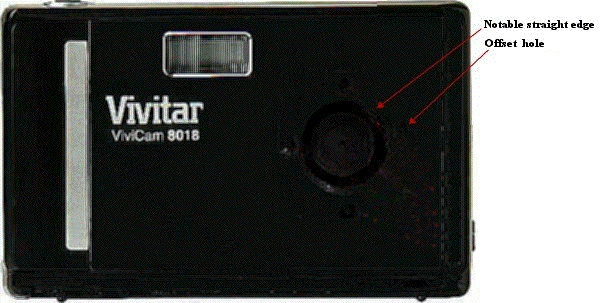
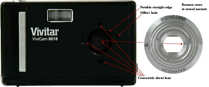
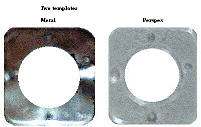
The initial plan was to unscrew the barrel from the rim of the ocular and site the plate on one of the intermediate threads. The problems associated with this method were threefold. The eyepiece rims obscures the mounting fixings. The hole in the main camera cover is smaller than the ocular rim. The metal is too thin to provide for a screw thread. The notable straight edge on the picture below shows clearly the first problem. |
|
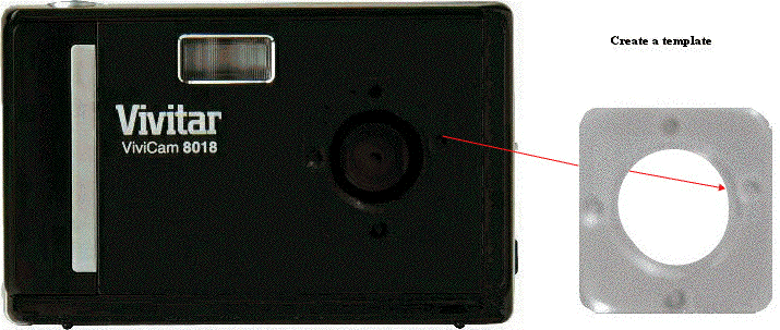
Having created a metal template, I proposed a solution of simply recreating the plate with greater depth using Perspex™. This might have allowed for some kind of thread, or for the routing of a stepped hole to accommodate the rim and then smaller to accommodate the barrel. The problem I discovered at this stage was that the rim of the ocular exceeds that of the patterned lattice of mount fixings. I also discovered that one hole is offset from the other three of the camera face. So basically these simple approaches were not going to yield a successful result. The following method describes the final and forth attempt at providing a fixed lens mounting for this camera. (My third attempt involved the use of a Hozelock™ tap adapter for screw threaded taps, and failed, due to the rim size being too thin. I saw the Clowns again that night, things were getting bad!) As I thought about the Clowns, I thought about the acrobatics, I started to see frogs leaping out at me, like Clowns trying to avenge themselves after failed dissections: I was becoming slowly, a Ranaphobe. |
Parts. |
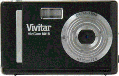
| The Vivitar™ Camera as it ships out from the High Street vendors, has no telephoto variable lens. Its fixed lens system makes it a perfect suited candidate for modification with an affordable price to match.
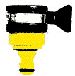
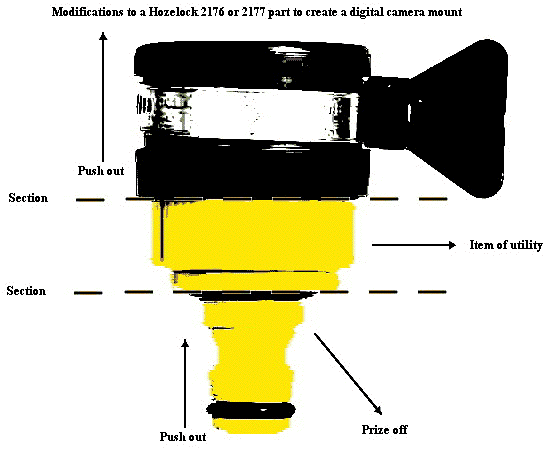
The Hozelock™ 2176 or 2177 component will become part of our Camera lens mount.
A Vivitar™ Camera with a Hozelock™ microscope ocular adapter affixed. The completed assembly does not interfere with the normal performance of the camera, but provides for mounting on oculars.
|
Additional required parts include: a couple of small Panel pins, a section of Rubber Hose from the a car repair shop, 28 mm internal diameter, 35 mm outside diameter, a few small Sewing needles, a friendly Optician with a range of small Spectacle screws: (for me that was Boots™ the Chemist). Required tools include: some means of heating: a Bunsen burner or lighter, a Small Junior hacksaw, Araldite Rapide™ or Quick set Epoxy resin, a Hot Melt Glue gun, Snipe nose pliers, Pliers, a small Craft hammer, a Set of needle files, 120, 180, 400, grade Emery / wet and dry, Silver wadding polish, or Duraglit™ for Silver, a Set of miniature screwdrivers. Some form of Lock knife: Opinel™ recommended (I hate Clowns the sell knives that fold in my hands). A Large Flat file, a Large Round file: ? Perhaps, a large round rasp. Skill: to make a good job of this you need patience and skill. If you have neither of these, then perhaps a good school physics technician can assist, or someone familiar with practical, not theoretical, engineering. The task can be completed in a morning and afternoon given the materials at hand. Most of these items are readily available, given even the remarkable void of serviceable parts in this part of SE England where I am currently located. |
Method of construction. |
1) The best place to begin is by cutting through the Hozelock™ part as shown in the diagram below, using a junior hacksaw. You might want to start by removing it from the tap first, (but I found it much more fun connected with the tap turned on!) This should leave you with the centre most part of this item.
2) Face the lower most side with a gradations of flat files from large to needle files and finish smooth with emery papers, so that these edges are true, flat, and oblique. 3) Remove the front fascia cover of the Digital camera: it just pings off with your fingernails.
Notice that the lens is central about the three left most holes with the right most hole offset. The round curvature of the hole in the front metalwork of the camera is also deliberately misleading. The top most hole is oblong, to accommodate a small hook. The lower most hole is very shallow to accommodate a pin. The equatorial holes provide the main means of fixture for the camera, and these holes are screw threaded to accommodate an B.S. thread just under 1.2 mm. Diameter. This aspect of affixing is precise, and requires the correct threaded spectacle screws to fit the camera. Do not cross thread this item in trial by forcing the wrong screw into place. Your local camera specialist or opticians will be able to source these parts for you from stock items. 4) Create some form of template by placing an acetate overhead projector sheet in place over the camera front panel. Grip a small sewing needle in some snipe nose pliers, and the tip of the needle in a flame. Once hot this can be quickly used to pierce through the acetate sheet so the holes presented in the sheet are exactly aligned to the mountings on the camera fascia. Note the top hole is oblong, the right hole is off centre to the lens. 5) With a fine solvent artisan marker pen, draw a vertical line from between the centres of the top and lower hole. Mark the centre of this line, at the mid point which will exactly align to the centre of the left most hole. Where these three lines meet, is the centre of the lens. Check you have correctly sited these markings using the camera fascia as your principal reference.
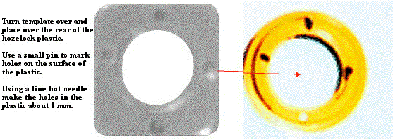
6) Turn the template over by lifting the left side to right NOT bottom side to top. Looking at the rear of the Hozelock™ part, mark small indentations on the rear surface using the same hot needle process you used to mark the acetate template. The markings should show the left hole higher than the right hole, and when the oblong hole is top most when viewing the back of the Hozelock™ part.
|
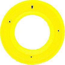
| 7) The markings on the rear of the Hozelock™ should look like this. |
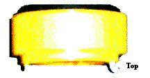
8) Using a hot sewing needle mounted in snipe nose pliers make two full through indentations on the equatorial East and West sides of the Hozelock™. Make two partial through indentations of 2 mm depths at the top and bottom of the rear surface of the Hozelock™ part. Repeat this process using a 1 mm panel pin. 9) Place a 1.5 mm diameter panel pin in pliers and fold it to an angle of 90 degrees in the centre, using snipe nose pliers and a small craft hammer. Top and tail the pin, with the pliers or with a junior hacksaw, so only the angle remains. One end of the nail should be about 6 mm the other 2 mm. Heat the 6 mm end and insert it into the top hole in the Hozelock™ so the bent end faces outwards, top most or northwards, whatever. Remove the pin when slightly cool. Mix epoxy resin or Araldite™ together and affix the 6 mm end into the top most hole so that there a gap just oversize to that on the camera front panel. Don't worry about the size of the 2 mm part or the diameter of the pin itself, but do ensure that the formed part is located so the bent part faces out most, and the gap between the rear Hozelock™ face and internal part of the pin parallel to it is large enough to accommodate the panel fascia. 10) Repeat this exercise for a 1.5 mm diameter straight panel pin about 6 mm in length but without the angle. This should be placed in the lower hole to form the lower most stud. Secure in place using Araldite™. At this stage the Hozelock™ part will appear as the picture below. Leave the part until the glue is dry.
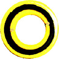
By this point you are probably thinking that this will never work, perhaps doubting your capacities: perhaps your suffering a bit of Coulrophobia yourself thinking this was written by a Clown. That seems like a good enough excuse for a decent helping of lunch and some Macdonald's™ therapy, while the glue dries. If you stick with this plan, you will achieve a very precise part. Don't be tempted to skip using the Araldite™ quick set epoxy, and leaving the fixings to heat alone. Don't be tempted to using the hot glue gun for fixing these main pins. The Araldite™ will provide the most secure form of bonding suited to these materials. 11) Ok so you've come back to examine the Hozelock™ after lunch. With the glue now dry, it's time to find out just how accurate you have been, you will be surprised. The top hook is over size, the lower pin is too big, perhaps a bit off line: no worries. Dig out the fine flat needle file and face the side of the panel pins so they are flat, of course this is the time to make those minor adjustments in filing so the pins are correctly centred. It is best to start with the hook first. Face the East West sides of the hook flat, to the width of the oblong hole. Square the internal bend of the hook so it is exactly right angled. Square the exterior face of the hook flat. Blow off any loose filings from the part and offer it gently to the hole in the camera. It should just tuck in the hole. The length of the 2 mm part will have to be filed down so as to fit snug in the hole. When a correct insertion is finally made, face the surface edges of the Hozelock™ rear surface with a file, to remove the surface of Araldite™ so the hook fits tight flat and snug. Once the hook is finished start working on the stud at the bottom side, follow the similar practices of squaring the stud, reducing it height and achieving the exact alignment in place on the camera fascia. 12) Now you are really over the worst part, it's all down hill from now on. With the Hozelock™ mounted over the fascia, you should be better able to look at the equatorial holes, and their alignment. Use a small round needle file to make the very small adjustments required for the screws to be easily inserted in their equatorial locations. You will have a number of methods available to you for any corrections, perhaps the best one is the use of a hot panel pin to move the holes slightly. Finally you will have to countersink the front surface of these holes so the opticians screws sit flush in their holes. The picture below shows the Hozelock™ adapter with these screws in place.
14) By now you will have realised that the Hozelock™ 2177 part is about 37 mm outside diameter, and 35 mm internal diameter. You will probably not have noted that there is a small taper to this interior surface. On the other hand the standard oculars are 23.2 but the rims are 27.8. This difference means that there is a requirement for some kind of flexible buffer. I achieved this buffer using a piece of Automobile hose pipe: (probably one some old kind of Volkswagon™ supplier found unnecessary after finding they had lost the special spanners needed to change the wheels in a lay-by.) The exact part number of the item, before I get a torrent of Beastly Boys at my door wondering if I got the hose pipe from the radiator on their car, is 4272-10280 from Canterbury motor factors, parts direct listed as from NKG Fram Gates Varta TRW Delphi Luk Kyb, whatever that means, all we know is it is rubber, it has a 28 mm internal diameter and a 35 mm outside diameter and was specially selected for by the man who knows about these things. It is a pretty close fit, but not exact. 15) The pipe has to be cut to about 1 mm deeper than the receptacle part of the Hozelock™ into which it fits. This sounds easy, don't even go there, get a mechanic to cut the pipe, with their tools if you can. Mr. Latham of Deimos™, Zincsmart™, and Latham marine (you can find them on the web), is a marine engineering precision engineering specialist who has managed to assist me with this task in between turning out Zinc Anodes for ships of Oddysseus, using skilled hands so exact and that I have not seen in the UK since the 1970's, and which put my humble abilities to shame, half of Ford Dagenham out of business and half of British Leyland out on strike for a cup of Tea. I guess many people reading this will know someone at their school or work place who can assist in the task of rubber forming. There are several methods of adjusting rubber. One I used to use often was Cyanoacrylate Adhesive activator (a solvent the medics use if someone puts Superglue on the toilet seat), which tends to melt everything known to man and beast. Another method would be a very rough craft rasp of some form, probably circular, Carbon or Teflon coated. It is a good idea to stretch the tube over a large pipe and grind the surface with a disk before applying it to automated equipment. A few people out there will be capable with a sanding disk, or angle grinders, but they are not for use by kids. In hindsight it would be better to use some form of cold cure rubber, or soft foam. In any case, having the pipe supplied to me by en expert motor factor it was close enough to be of service, and it was useful to be able to compensate for the taper in the mould by shaving 1 mm from the exterior surface at a gradient, and 1/2 mm from the interior surface, so as to accommodate the minor differences in rim sizes of 27.8 mm oculars. The trick to doing the interior surface is to turn the cut band inside out. 16) Fixing the tube to the Hozelock™ is tricky. The right bond to use is hot glue, from a glue gun. Cyanoacrylate Super glue tends to vaporise and leave the plastic surface smeared, so use Hot Melt glue. Fold the rubber smaller than the diameter of the tube, and dab the surface face end of the rubber with a small bead of glue. Quickly (under 30 seconds) push the tube into the wider end of the Hozelock™ part. When cool, fold the sides of the tube down in part to allow the application of a dab of hot glue, working round the circumference of the tube, in rotation, dabbing and sticking on the way. To get a fully secured fitment, apply hot air from a hot air blower to the rubber surface taking care not to melt the Hozelock™. This should allow the rubber to be fully bonded to the two materials. 17) Tidy up any excess glue from the front surface of the adapter. Polish the entire completed article using a Silver wadding polish, like Duraglit™, to remove scratches that might have occurred in the plastic. You can polish the rubber too, grading down from rough to smooth files, needle files, emery, and wadding. 18) Mount the adapter in the camera using the screws.
19) The finished adapter looks like this.
A Final thought on this adapter. Relief, I finally managed to achieve a solution: this year I might really find myself enjoying the UK's never ending obsession with banning hose pipes! Self criticisms? Yes, perhaps I could have found an exact size rubber tyre that did not require adjustment. Perhaps, I could have had the item made entirely from metal, turned on a lathe. Perhaps? But I don't have a lathe, a workshop, and I only have only a few tools and my hands. I value people's time, and their efforts, and I am extremely thankful for the support in small requests I make to very busy people, but in the large part, I am fellow, much dependant on my hands and skills alone. I cannot help feeling that having the thing made entirely as a custom order would be expensive, I doubt I could say the time would be less than £100 pounds, were I to have to detail and describe the requirements to a workshop, and that descriptive area is two fold costs. And the camera, what price? Under £30 from a supermarket, the Hozelock™, 1/6 th of the price of the camera! These things considered, it appeared to me to be the right thing to do, that is, to create the item from existing formed part items. I contemplate the time in these contexts: 3 days researching how to do this, and failing, and 1 day of making the item up. That to me is the expensive part. How can anyone possibly justify the cost of making such an item outside mass manufacture, given the price of mass manufacture of a wonderful camera like the Vivitar™ being under £30: it's a ridiculous absurdity, to say, in that context, that my whole days efforts, the whole research exercise, and the writing of this paper, is worth anything more than the market price, and that price, in real terms of mass manufacturing, is about one single pound. Like many out there, I would have gladly paid one pound extra on the price of the Camera item, to have it supplied with a proper fixing to interface to optics, but try as hard as could, they just never appeared. I shall finish now, where I began, I have offered a method and means of interfacing a Vivitar™ 8000 series camera to optics hitherto unavailable. Am I the Clown, or am I just the person experiencing Coulrophobia? It's a bit of a chicken and egg question I guess, I leave it to a few academicans to thrash out the solution, before I get notions of and thoughts of a big bird phopia. I feel a Macdonald's™ coming on, and while I am out at lunch, can I leave you with the faint hopes of optimism, that the next guy won't have to spend 3 days researching and interfacing a method of achieving this task, and that, perhaps, the next batch of Digital Cameras that ship out from mass production, will have a complete and universal standard range of mountings in the box. |
| ||
David Christmass Mailing Address: Room 1, No 2, Victoria Road, Canterbury, Kent, UK. CT1 3SG. ©David Christmass 2011 |
Published in the June 2011 edition of Micscape.
Please report any Web problems or offer general comments to the Micscape Editor .
Micscape is the on-line monthly magazine of the Microscopy UK web site at Microscopy-UK
©
Onview.net Ltd, Microscopy-UK, and all contributors 1995
onwards. All rights reserved.
Main site is at
www.microscopy-uk.org.uk.