Using High Power LEDs in Epi-illuminator Systems
Robert Pavlis
Girard, Kansas USA
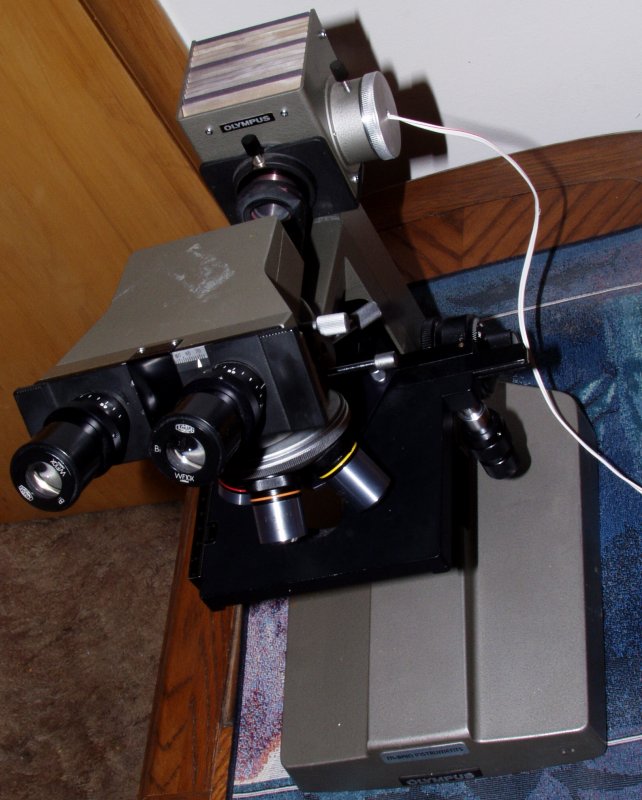
The use of light emitting diodes as illumination sources has been discussed in several recent issues of Micscape. Using them on metallurgical microscopes (and other microscopes with epi-illumination systems) presents special challenges because light sources for this type of instrument must be rather intense. We will examine here a design of an 5 watt "star LED" illumination system for an Olympus BHM metallurgical microscope.
As has been pointed out previously, LEDs have several advantages over tungsten filament lighting sources:
LEDs do have some disadvantages:
Any design that incorporates LEDs bright enough for epi-illumination systems thus must have adequate provisions to carry off the excess heat produced. Five watt LEDs give off so much heat that they can only be run a few seconds at full power without risking damaging them from overheating unless they be attached to some sort of heat sink. For this project I used a 5 watt "Star LED" (These cost about three times as much as 3 watt ones, by the way. Recently a new model called K2 has gone into production. They are much less expensive and brighter! But at this point in time it is difficult to find a vendor with them in stock. These should be available in a few months.)
The standard Olympus BHM epi-illuminator uses a quartz halogen lamp. Like most quartz halogen microscope systems the bulb is held in a cylindrical holder whose axis is perpendicular to the axis of the optical system. The illuminator housing has adequate provision for air circulation to prevent overheating.
Any LED illuminator must duplicate the geometry of the original quartz halogen system, and must fit in the same 40mm diameter aperture holder. I thought about these problems for some time before attempting to build such a system.
A very important design consideration is what metal to use for the LED holder. Copper would be best, but it is extremely dense, rather expensive, and difficult to machine. Although brass and bronze are copper alloys their conductivity is only about a quarter that of pure copper. Furthermore, these alloys are also very dense. Aluminium thermal conductivity is quite high. It is light, and some alloys are not especially difficult to machine. Thus aluminium seemed to be the best compromise. (Besides I had a piece of an easily machinable aluminium alloy in stock!)
The image below shows the design. Note the fins behind the LED. These fins dramatically increase the surface area of the device so that air circulating through the lamp house can cool the device very well. Although it is not particularly difficult to machine a piece of aluminium like this, it does require at least three shop machines: A lathe, a bandsaw, and a milling machine.
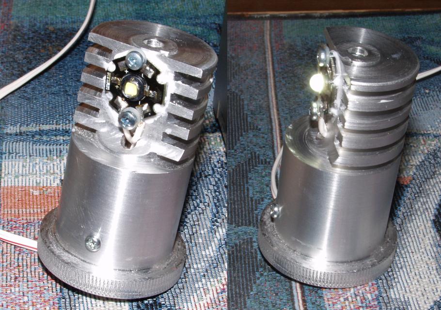
The holder was machined as follows:
I power the LED with a so called 1.5 amp "Universal" power supply for electronic gadgets that can be set to deliver voltages between 3 and 12 volts. I use a 5 ohm resistor in series with the LED as a current limiter. At some point I should make a better power supply, but this is very adequate.
The Olympus BHM provides both the epi-illumination version of bright field and dark field. Standard objectives will NOT fit in this microscope because the mounts must be larger than normal to accommodate the light coming in from around the sides of the lenses when they are used in dark field mode. In the "bright field" mode illumination passes through the same lens used for illumination. This obviously results in some scattered light.
Brightness is more than adequateit is outstanding. Digital photography also works quite well. Some of the images below have slightly darkened edges, this is due to the adapter employed, rather than to any fault of the illuminator. When properly adjusted it is at LEAST as uniform as with the original quartz bulb.
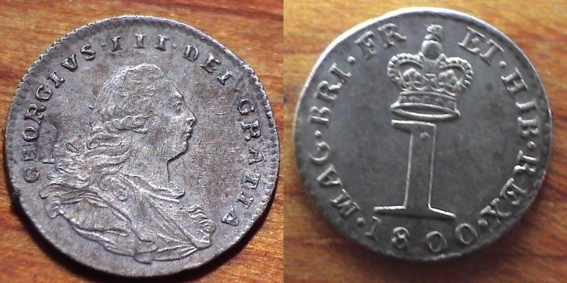
I decided an old coin would be a good subject for images taken with the system. I searched for the smallest coin I could find, and that turned out to be a silver Maundy penny dated 1800. the smaller the better! These tiny coins are only a few millimetres in diameter! The image below this text shows the obverse and reverse of this coin taken with an extreme closeup lens, not the microscope:
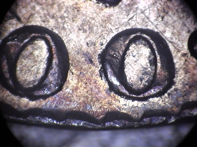
The image directly below this text shows the same tiny penny with a 6X objective and illumination through the lens: (This objective has only provision for epi-illumination through the lens.)
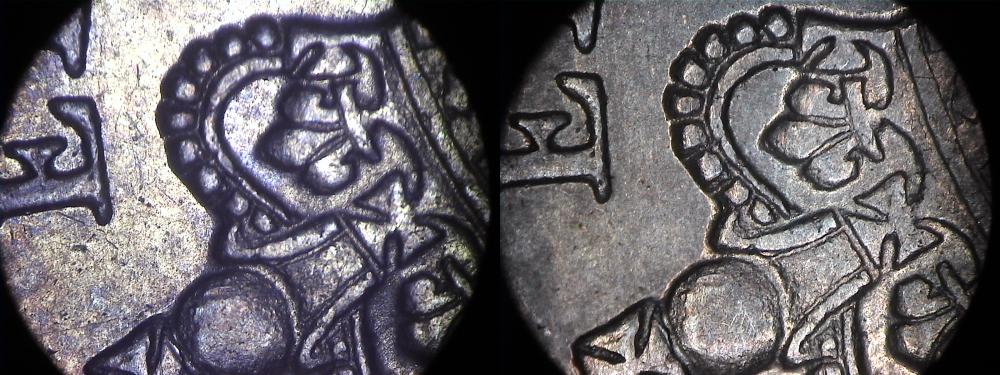
The image below this test is taken with a different low power objective, 5X. The image on the left is through the lens bright field illumination, the one on the right is utilising side illumination, the epi-illumination dark field equivalent.
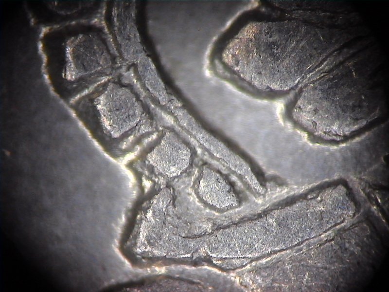
The next image shows the coin using a 10X objective with "dark field" illumination.
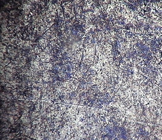
The following image shows the same coin using a 20x objective with "bright field" illumination. In spite of being illuminated through he objective, the contrast is still quite good.
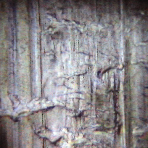
The final images shows a piece of aluminium stock using a 100x oil immersion lens. (I did not want to put immersion oil on this somewhat rare coin.)
People who have not used microscopes equipped with LEDs are often surprised by the natural colours, and the way that colour distribution is unchanged when the light source is dimmed. At this point it seems likely that almost all new microscopes will be utilising these devices in a few years!
All comments to the author Robert Pavlis are welcomed.
Microscopy UK Front Page
Micscape Magazine
Article
Library
Please report any Web problems or offer general comments to the Micscape Editor .
Micscape is the on-line monthly magazine of the Microscopy UK website at Microscopy-UK