|
|
A Gallery of Resorcinol Photomicrographs (using
a variety of illumination techniques) |
|
|
A Gallery of Resorcinol Photomicrographs (using
a variety of illumination techniques) |
The
compound known as resorcinol is much utilized in the chemical
industry. It is an unusually useful intermediate in the production of
more complex chemicals. Derivatives of resorcinol are found in
the light screening agents that protect many plastics from degradation
due to sunlight exposure, and in the dyes used to colour our
fabrics. The primers used to detonate explosives, flame
retardants, and adhesives used in the manufacture of tires for
passenger cars and trucks, all make use of resorcinol.
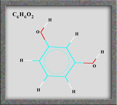
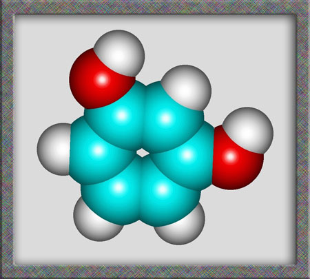
Aromatic compounds, of which
resorcinol is a member, are based on a benzene ring structure. As
can be seen from the following illustrations of the structural formula,
and molecular shape, resorcinol is a fairly simple organic (carbon
containing) molecule. Alternative names for the compound are
1,3-dihydroxybenzene and m-benzenediol. (HyperChem Pro was used to produce
the illustrations.)
In
the lab, resorcinol is supplied as a white (or slightly pinkish)
crystalline solid with high solubility in water and a melting
temperature of about 110 degrees Celsius. The crystals turn
faintly brown with exposure to air and light. Although it would
have been easy to produce an evaporation
specimen for study under the polarizing microscope, I chose
instead to prepare a melt specimen.
A couple of crystals were placed on
a microscope slide and covered with a cover-glass. An alcohol
lamp was used to heat the slide very gently, until the crystals melted
and formed a thin layer between slide and cover-glass. When the
melt solidified, it was examined under the microscope.
Note:
The MSDS safety document for
resorcinol describes the very unpleasant consequences of a failure to
handle the compound carefully.
Danger!
may be fatal if swallowed. Harmful if inhaled or absorbed through skin.
May cause methemoglobinemia*. Affects cardiovascular system, central
nervous system, blood, spleen, liver and kidneys. Causes severe
irritation to skin and eyes. Causes irritation to respiratory tract.
May cause allergic skin reaction.
*
Methemoglobinemia is a condition in which the iron in the hemoglobin
molecule (the red blood pigment) is defective, making it unable to
carry oxygen effectively to the tissues.
My slides were all prepared in a
fume hood in my chemistry classroom. I do not recommend producing melt
specimens of this compound in the home environment!
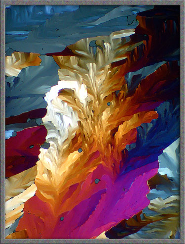
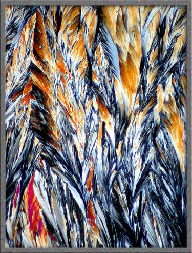
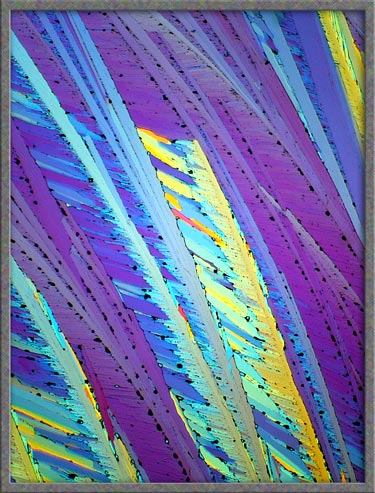
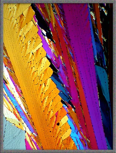
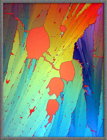
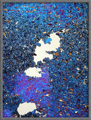
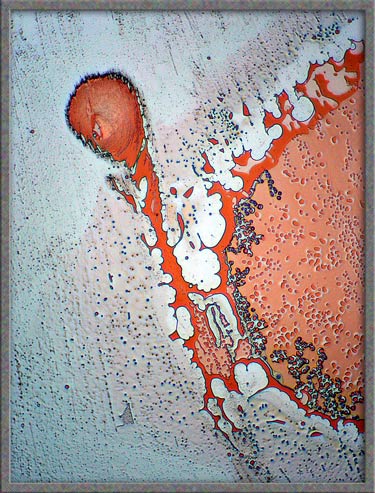
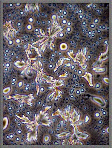
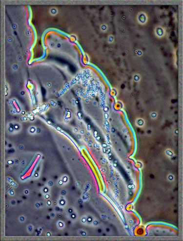
The first image in the article, and
the one below, show typical crossed-polar
images. The gray areas are thinner sections of the crystal layer
formed during re-solidification of the melt.
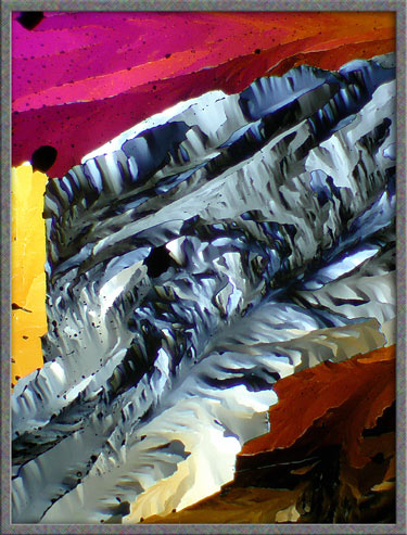
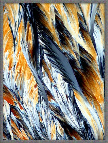
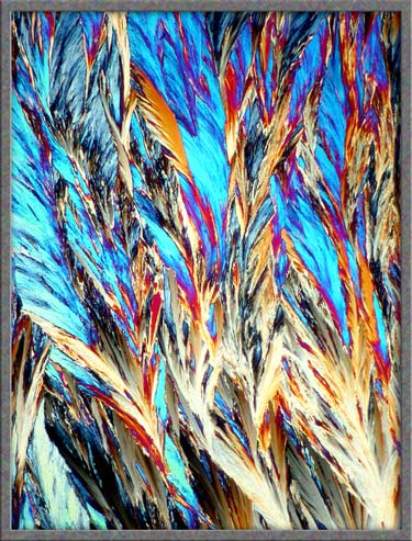
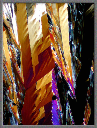
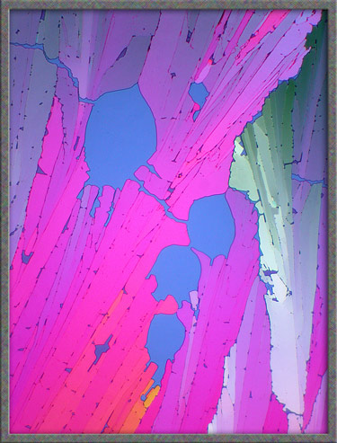
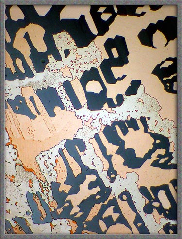
Feathery
structures often form as the melt solidifies. Note that the image
on the right is a higher magnification view of an area near the top
centre of the left image. The third image uses a compensator,
(lambda/4 plate) to produce an alternative colouration.
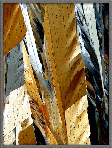
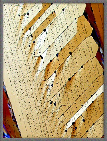
Many
of the crystals formed contain tiny black areas, probably produced by
overheating the slide and causing tiny bubbles (voids) to form that
look black between crossed-polars.
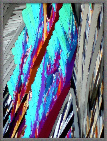
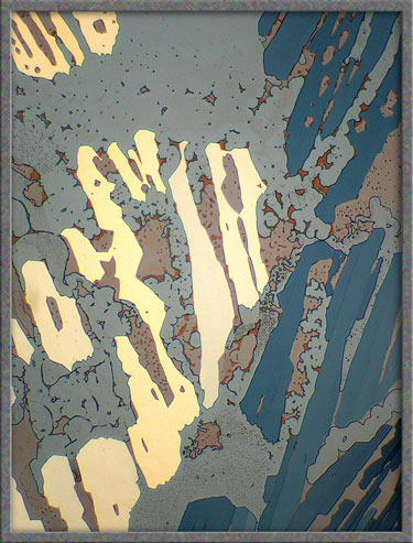
The
tiny voids seem to form along fault-lines in the crystals. This
can be seen more clearly as the magnification increases in the three
images below.
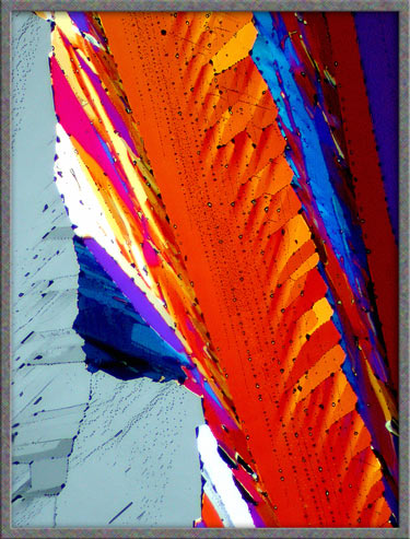
At a very high (relatively
speaking) magnification, the crystal layer can be seen to be literally
peppered with imperfections. (Right image)
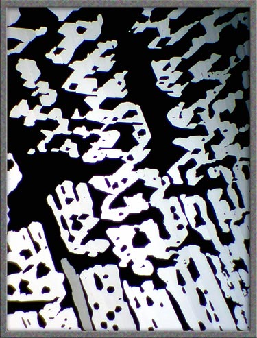
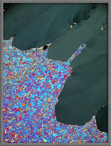
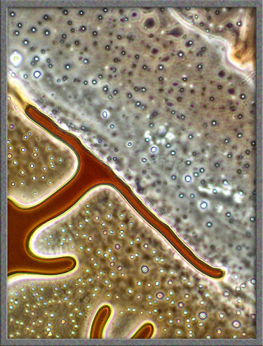
The
following two images illustrate another phenomenon seen with melt
specimens. Over long time periods (several months to years), some
of the solid compound can sublime directly to a gas. This leaves
voids having a different appearance than those mentioned
previously. (The background in the right-hand image is gray
rather than black due to the fact that two lambda/4 compensators were
used to produce elliptically-polarized light, rather than the normal
plane-polarized variety.)
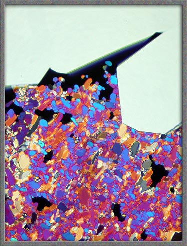
By
using a combination of lambda and lambda/4 compensators, it is possible
to completely change the appearance of a particular field on a
slide. The lambda/4 compensator was rotated to produce the two
images below.
Near
the edge of the cover-glass, a rather amorphous field of small crystals
often forms. (This ring at the edge of the cover-glass may cool
more quickly, as it has not been directly heated by the flame of the
alcohol lamp. Thus there is insufficient time for larger crystals
to grow.)
Higher
magnifications reveal details in the amorphous areas.
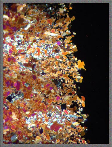
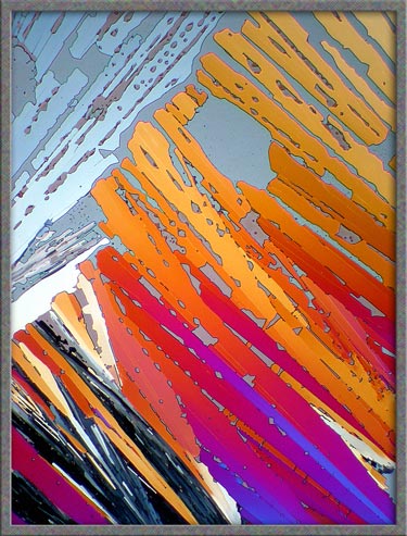
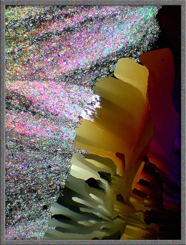
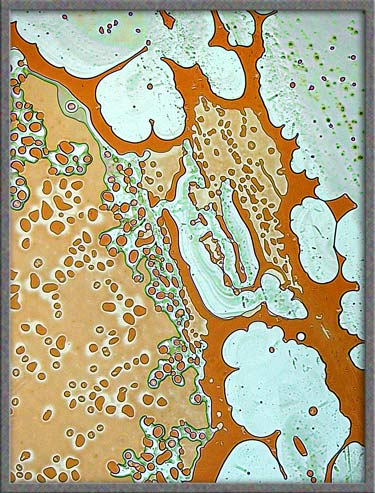
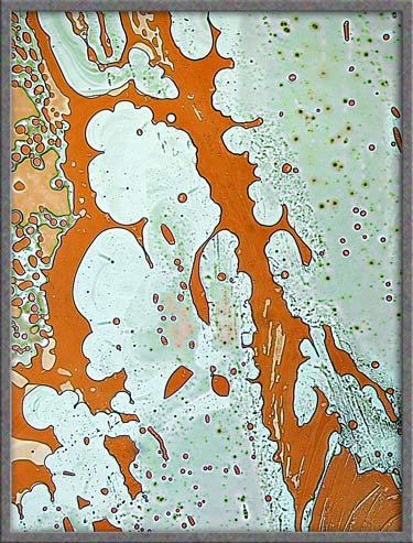
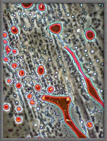
The
five images that follow show areas at the very edge of the
cover-glass. The first, fourth, and fifth images, (those with an
orange background), were produced using ordinary transmitted light illumination.
Note however, that the auto-level
command in Photoshop was used
to produce the strange effect. (Some purists may object to the computer processing of images, but
the technique sometimes results in striking images such as the first
one.)
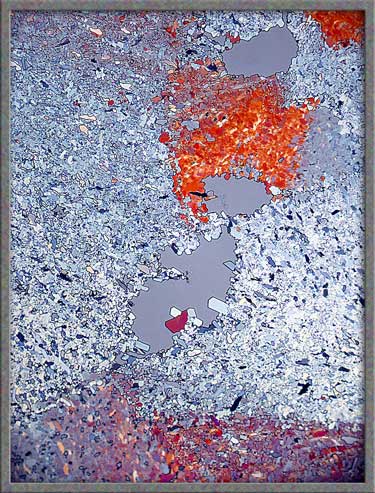
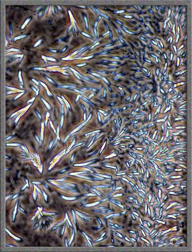
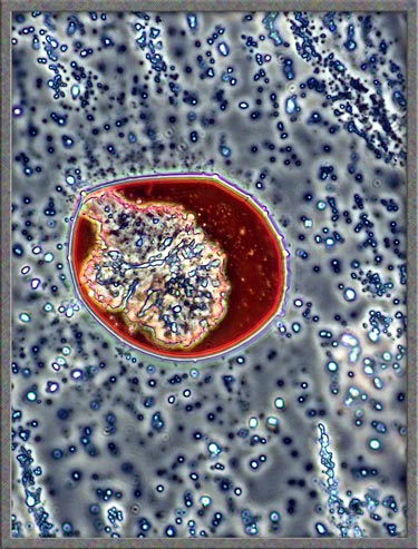
As
mentioned in earlier articles, I often ring the cover-glass on crystal
slides with finger-nail polish. In some cases, the solvent in the
polish dissolves the crystals at the very edge of the
cover-glass. Over a period of time, as the solvent evaporates,
crystals re-form in new and interesting ways. The perfect way to
study these crystals is to use phase-contrast
illumination. Typical fields are shown below. (Note
that the contrast has been increased in Photoshop.)
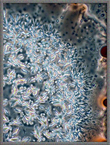
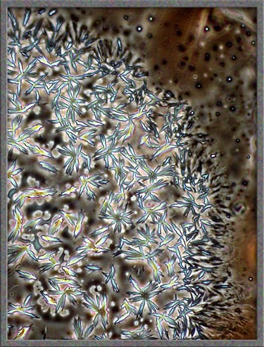
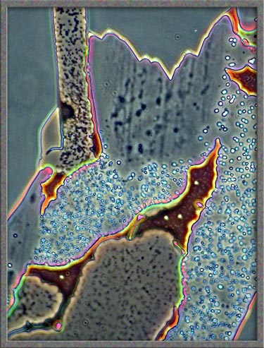
This
same technique has been used to obtain the following images of fields,
slightly farther from the edge of the cover-glass. (The bright
colours in several of the images are produced by interference
phenomena, as a side-effect of the technique.)
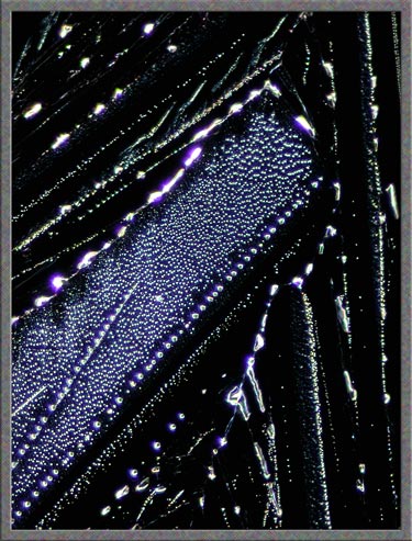
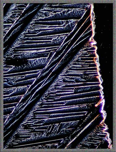
Finally,
several dark-ground illumination
images of resorcinol can be seen below.
Although
resorcinol is an unpleasant compound to work with, it often produces an
interesting array of crystal structures to investigate.
Equipment
The images in the article were
photographed using a Nikon Coolpix 4500 camera attached to a Leitz
SM-Pol polarizing microscope. Images were produced using several
illumination techniques: dark-ground, phase contrast and polarized
light. Crossed polars were used in all polarized light
images. Compensators, ( lambda and lambda/4 plates ), were
utilized to alter the appearance in some cases. A 2.5x, 6.3x, 16x
or 25x flat-field objective formed the original image and a 10x
Periplan eyepiece projected the image to the camera lens.
Published in the July
2006 edition of Micscape.
Please report any Web problems or
offer general comments to the Micscape
Editor.
Micscape is the on-line monthly magazine
of the Microscopy UK web
site at Microscopy-UK
© Onview.net Ltd, Microscopy-UK, and all contributors 1996 onwards. All rights reserved. Main site is at www.microscopy-uk.org.uk with full mirror at www.microscopy-uk.net .