THE CHALLENGE OF GRINDING LENSES FOR SINGLE LENS MICROSCOPES
By: Alvaro Amaro de Azevedo - (Brazil)
1.) INTRODUCTION
In my previous article (1), I have discussed the optics of ball lenses for single lens microscopes showing that it’s possible to obtain surprisingly good images from low budget materials and resources. For a long time I have made these lenses using hair-like thin glass threads that upon the heat of a flame would become symmetrical spheres. As to my knowledge, I thought that achieving different type of lenses was not feasible for an amateur and would only be possible using highly sophisticated modern machinery.
However, after reading the article: “The Microscopes of van Leeuwenhoek” (2) by J. van Zuylen, I was amazed to find that most of the still surviving 9 pieces basically work with ground lenses instead of melted ones as I supposed. In the article, the author explains how the lenses might have been made and he describes how he did succeed on grinding some lenses himself with the help of Mr. J. C. P. W. Gerwig, an optician with 25 years of experience. Having the knowledge of some of the basics, I was greatly excited with the idea that I could try out on making ground lenses and then I would have a chance to see what the images produced would look like.
2.) – MATERIALS AND TOOLS
Anyone who has ever read about lens grinding techniques is aware that the main resource for succeeding is the grinding powders. These are a series of abrasive powders that have to be employed, firstly to generate the curvatures and then for making them smoother to an almost polished finish. The grade may vary from grit 80 up to grit 2000. Generally they are made of carborundum (silicon carbide) but it’s possible to find those made from corundum (aluminum oxide). I honestly have no idea where such powders could be found locally but the article mentions that Leeuwenhoek might have employed sand and graded it by levigation. So that was what I did. The sand was collected from a nearby beach and then washed thoroughly. After it had dried, the sand was put into a mill where it was crushed for one hour. The resulting flour was then suspended in water and through levigation six fractions were collected. I named them from 1 (the coarsest) to 6 (the finest).
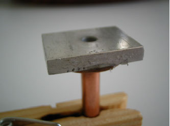
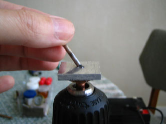
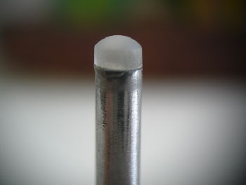
Then the next part of the project was the grinding tool. This consists of a concavity stamped into a metal block. The radius of the concavity will determine the radius of the lens curvature. I used a steel ball 4 mm wide to create a hemispherical hole in an aluminum block that was afterwards connected to a shaft.
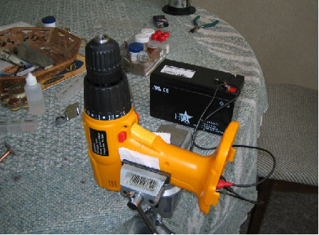
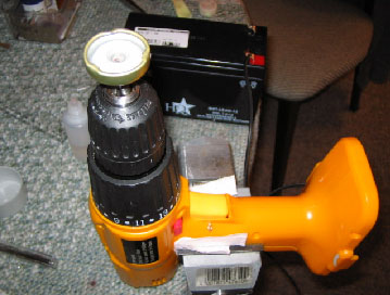
The tool was attached to a drilling machine permanently supported by a clockmaker's vice. Because the rechargeable battery of this machine wasn’t strong enough to keep up with the rather long grinding sessions I adapted a 7Ah lead-acid battery that has proven to be adequate to allow the whole operation to be accomplished at once. This setup was my improvised lathe.
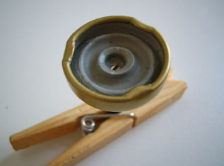
For polishing purposes, I tried to find the jewelry rouge (iron oxide) but it was in vain. Then I tried to smash a hematite stone and I got a powder that was too coarse for a good polishing powder. Then I made many attempts to find a good substitute and at the end of the day I made a polishing tool that doesn’t need powder to carry on polishing. My polishing tool just needed a few drops of water and it works on the principle that epoxy modeling material consists basically of a low hardness material (epoxy resin) in which there is embedded an abrasive powder (filler) of a sufficiently hard material to inflict abrasion. The geometry of that tool permitted the work piece being polished equally throughout the surface yielding a rather homogeneous polishing. The final polishing was always given by hand where the work piece was rubbed against a soft cloth soaked with metal polish powder (metakaolin).
3.) – DESCRIPTION OF THE PROCESS
Having now found all what it takes for the lens making process, I can introduce a summary description of the whole process:
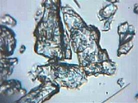
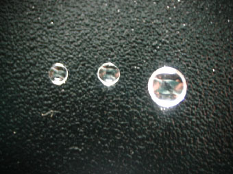
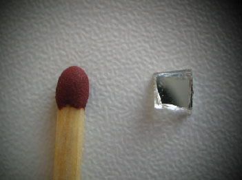
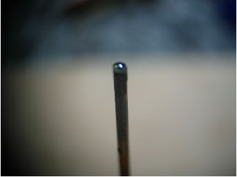
Cutting the glass: Once a glass was chosen, it has to be cut into a size approximate to the handle where the work piece will remain until the end. The flat glass can be cut by use of a glass cutter but it take several attempts until one gets skilled enough to cut good sized glasses. The picture below was made including the head of a matchstick just to give an idea what the size was all about.
Cementing the glass in the shaft: I have tried countless number of materials to cement the glass in the handle shaft but none have shown to work well. Then I evaporated an ordinary solvent based glue and kept it close to a light bulb to force the evaporation of the solvents. The resulting mass was strong enough to keep the work piece cemented during the whole process and could be softened by heat when it becomes sticky and adhesive.
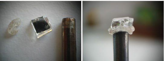
Making the blank: Once the glass square was firmly cemented in its handle then it can be ground with wet sandpaper. As the piece is gradually losing the pointed edges, the handle has to be spun between the fingers in order that all sides will be ground to the shape of the handle. In the end, the blank is born.
Grinding the blank: The work piece is brought to the tool, which has received a bit of grinding powder no. 1 and a drop of water. As the tool rotates, the work piece is positioned in the vertical direction and as the grinding process takes place, the work piece has to be spun between the fingers. The operation is maintained until the tool seems to drive smoothly as the grinding powder has all been lost and no real abrasion is taking place. At this point, a new bit of abrasive is added in the pit.
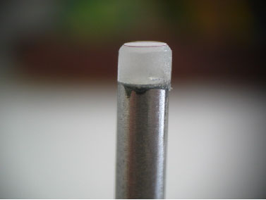
Refining the surface: Once the work piece’s surface was brought to a curved profile and no flat area can be noticed, the grinding powder has to be gradually replaced by the finer ones. The surface has to be thoroughly worked with each of the grinding powders and as consequence, the surface starts to get smoother and smoother. In the end of this step, the imperfections of the surface reach the minimum but the work piece is still translucent. No scratch or pit should be visible at this stage.
Pre-polishing: If the last step was performed accordingly, then next comes the pre-polishing step with the polishing tool. The work piece is kept vertical and is kept spinning slowly while the tool rotates in the lathe. Only water is used to lubricate the tool and with time, the friction felt becomes weaker and weaker as the surface gets polished.
Finishing: After the pre-polish step, the work piece becomes reasonably transparent but it still has imperfections throughout the surface. If the work was well done in the steps before, these imperfections are very shallow and will all disappear in the final hand-polishing step. This step consists of rubbing firmly the work piece against a wet cloth soaked on silver-polish powder. The movements are straight lines forth and back while the work piece is slowly spun between the fingers. It doesn’t take too long until an impressively glossy surface shows up. No imperfection or scratch or pits are noticeable and the resulting lens has the perfect optical surface. Once one side is concluded, then the other side has to be worked out in the same way.
4. SPECIFICATIONS AND PERFORMANCE
The 10 lenses that I have made by means of this process have the following dimensions:
Diameters: 3.3 to 3.0 mm
Curvature radii: 2.0 to 2.5 mm
Refractive index of the glasses: 1.54
Focal lengths: 1.85 to 2.30 mm
Magnifying Power: 108 to 135 X
These values are estimations as my measurement instruments are not accurate. The focal length values were calculated on basis of the The Lens Maker's Equation (see footnote 1) :
![]()
When mounted between two plates having apertures of 1.0 mm each side, the image has been shown to be amazingly sharp. Despite of the typical narrow field and the inevitable spherical aberration, the images were clear enough to allow even the minutest details of the subjects to be seen under examination indicating that the resolving power was beyond my expectations. I have made an assembly in order to be able to connect a webcam and afterwards capture the images that this arrangement can supply.
5. FURTHER DEVELOPMENTS
After I have learnt and mastered the technique of lens making, I set myself to a new challenge which consisted of scaling down the process and making lenses in smaller sizes as this would be a means to achieve higher magnifications. Because I didn’t have smaller steel balls to make new tools, I thought to use a different strategy, making a glass bead by melting glass threads and grinding one of the faces using the 2 mm radius tool.
I started by trying out a glass bead 1.5 mm wide, which represented approximately the half the size of the lenses I was making before. For that, the handle had to be replaced by one 1.5 mm in diameter.
Gluing the work piece to the handle was found to be rather more difficult as the size of this piece was smaller. It took quite some time and practice until I could learn how to do that, but then it turned out that grinding had become a lot easier as the surface was just ¼ of the original size. The first lens made this way was well done, however a failure in the inspection of the quality of the bead was the reason for the problem found afterwards. There were air bubbles in the piece and the quality was inevitably compromised.
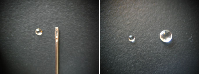
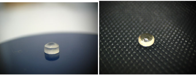
The pictures above are meant to compare the size of this lens and a needle and the predecessor lens. After replicating this process a few more times, I could make good quality lenses at this scale of size. The image did prove to be superior to those rendered by ball lenses as the aperture could be wider thus increasing the resolution.
By calculation, this lens should have focal lens = 1.0 mm yielding magnifications about 250x.
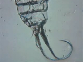
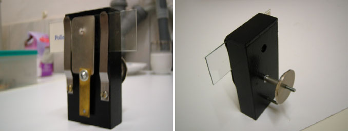
At this stage, I was wondering whether it would be possible to make an even smaller lens using the very same concept and technique. So I launched myself into an attempt to start from a glass bead about 0.8 mm wide. Initially, I thought I would get nowhere, but despite my original suspicion I endeavored to continue. I fused a handful of beads having that dimension and for several attempts, I wasn’t even able to make them stick on the tip of the handle, so awkward was it to manipulate them. The solution was to assemble a guide system in order to hold the bead steadily and firm while a track suitably placed would present the handle in the appropriate way and ensure that both of the pieces were correctly arrayed as shown below:
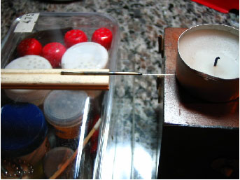
Although the guide system helped to glue the two parts altogether, I soon realized that they were not sufficiently stuck to one another in order to endure the steps of grinding and polishing as required. At this point thought I'd got to a dead end. However after thinking more about it, finally I found a solution. The tip of the handle had to be concave, so that the bead would fit more perfectly and the glue would have far more efficiency. It did work making it possible to go through all the required steps even despite the fact that the work piece was barely visible.
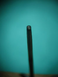
The output of this laborious work was a lens with the following specifications:
Major radius………….. = 2.0 mm
Minor radius…………...= 0.4 mm
Diameter………………= 0.7 mm
Focal length…………...= 0.6 mm
Magnification…………= 400 times.
(This equates to a very high magnification, so probably considerably overestimated. See footnote 1.)
The lens as described above was mounted in a seat and placed in my single lens microscope. The image observed by means of this lens seemed to me superior in quality compared to its ball shaped counterpart that I have started with, showing that it is possible even using crude resources and only basic household items to grind and polish such small work pieces. All it takes to accomplish such results is knowledge of the steps of lens grinding, persistency to restart as many times as necessary learning from the mistakes and some creativity to improvise methods and tools to carry on each of the required steps. The results will be worth all these efforts.
6.) COMMENTS AND CONCLUSIONS
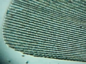
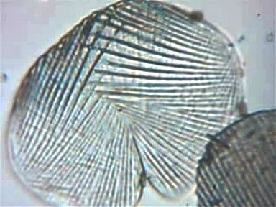
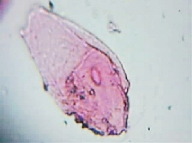
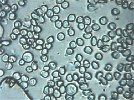
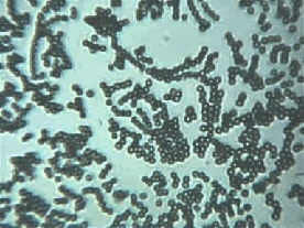
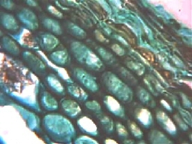
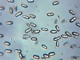
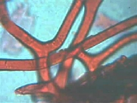
There have been many improvements in the construction of my further lenses afterwards. I learnt to work with thinner handles and created more accurate methods for inspecting the polished surfaces during finishing. I was able to grind lenses somewhat smaller in size for higher magnification. Some of the images below were captured through these lenses and they reveal remarkable sharpness and definition. The main advantage of ground lenses are that they can focus at longer distances compared to the same magnification from ball lenses and thus, I could capture images from already mounted slides that wasn’t possible before. I also noticed that ground lenses allow wider apertures and as consequence, the images seemed to be brighter and higher in resolution.
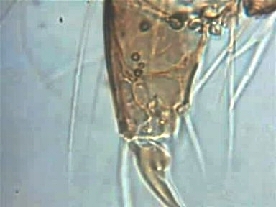
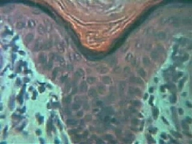
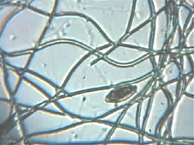
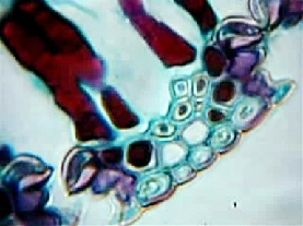
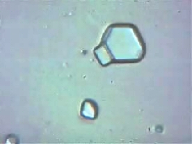
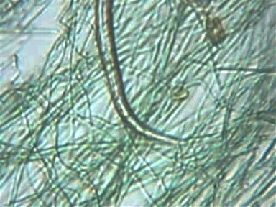
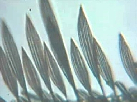
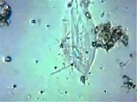
7.) – GALLERY OF IMAGES
(see author's footnote 2 on image size).
|
|
|
|
|
Above and left: Lens used focal length f = 1.0 mm |
|
|
|
|
|
Above and left: |
|
|
|
|
|
|
Above: Lens used focal length f = 0.7 mm
|
|
|
|
|
|
|
|
|
|
|
|
|
|
|
|
|
|
Above and left: Lens used focal length f = 0.6 mm
8 – FINAL NOTES
The images displayed above were corrected for contrast and brightness to better approximate to what can be seen under the microscope lens. No magnifications were indicated as I could not find an efficient and reliable way to calculate them. Lenses of different focal lengths were employed and some images correspond to higher magnifications than others.
Comments to the author Alvaro A. de Azevedo are welcomed.
9 – REFERENCES:
1) – Exploring the Possibilities of Single Lens Microscopes. Micscape, October 2005, http://www.microscopy-uk.org.uk/mag/artoct05/aalens.html
2) – The microscopes of Antoni van Leeuwenhoek, J van Zuylen, Journal of Microscopy, 121/3, 1981, 309-328.
Footnote 1: The lenses cannot have their focal lengths accurately calculated by thin lens equation as there is a thickness that has to be considered. I made simulations using the calculator from the website: http://hyperphysics.phy-astr.gsu.edu/hbase/geoopt/imgpri.html and as thickness (D) increases, the focal length shall increase too. The idea was just to make an estimation as the real value would require measurement methods out of my reach.
Footnote 2: I don't have any subject whose dimensions are accurately known to me except the blood cells smear slide. It's known that a human red blood cell is typically 7.7 micron wide and this can give a clue to those who would like to estimate the field view of the images. Based on this feature, the width of the field of view is about 150 microns which seems to be consistent when you look at the picture of a human hair that usually is reported to have an average thickness of 70 microns. So if I would take a guess, I would say that the images depict an area 110 x 150 micrometers when using the higher magnifying lens. Micrometric rules or other precise grids are not available for me here.
Update:
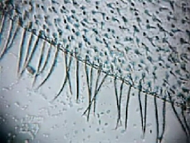
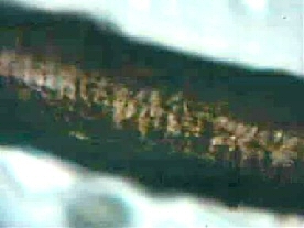
Field of view calculation. I obtained a stainless steel screen (a very thin one) and carefully
detached one of the strands of stainless steel. Then I put it in a precision
micrometer (accuracy of +/- 0.005 mm) subdivided into 0.01mm
divisions.
After measuring the wire gauge repeated times, I found an average
measurement of 0.05 mm, therefore it's 50 micron wide. I recorded a picture of this
wire using my 0.6 mm lens and the result is shown below. It's worth saying that the measurement was somewhat
higher than the measurement sensitivity of the
instrument (it was repeated a few times giving similar results with a variation
never exceeding 0,01 mm).
Considering this result, the calculation of the
field of view seems to be consistent with my original estimation and confirms
that the field of view in the pictures using 0.6 mm lens might be indeed 100 x
150 micron. I don't know if a procedure like this could be
considered acceptable but I'm open to any questions or argument.
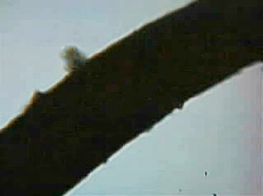
Image
of ca. 50 micron width wire taken with f=0.6 mm lens.
Published in the January
2006 edition of Micscape.
Please
report any Web problems or offer general comments to the
Micscape
Editor.
Micscape is the
on-line monthly magazine of the Microscopy UK
web
site at
Microscopy-UK
© Onview.net Ltd, Microscopy-UK, and all contributors 1995 onwards. All rights reserved. Main site is at www.microscopy-uk.org.uk with full mirror at www.microscopy-uk.net .