Being in the professional science
photography business, I often get asked to photograph the strangest stuff
using some very weird lens combinations. Lately, I was asked to take
some motion pictures of microscopic animals. So I set up the microscope
and attached it to a 35-mm motion picture camera but how do you measure
the exposure?
A typical answer would be to
use a standard film plane meter, but such a device would not fit my situation,
and I would still have to perform a calibration on the device.
The answer to my problem was
to simply build the type of meter I needed and then calibrate the device.
There are a number of photosensitive
electrical devices manufactured, and used. I happened to pick up
several photodiodes from a local surplus house. Photodiodes give
electricity when exposed to light. A standard photometer would take
the voltage and put it into an analog circuit to convert it to a readable
f-number for a certain film speed. I would be using the meter with
100 ASA film with a set exposure of 1/50th of a second. The majority of
photodiodes give off a relatively small voltage of several hundred millivolts.
In the old days of analog voltage meters reading this small voltage would
be a problem, but modern digital meters will easily read such a voltage.
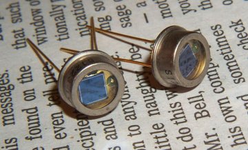
Two photodiodes on newsprint to
show size.
Taken with a Kodak DC290 with
a macro lens
Many different photodiodes will work
as a light meter, but the silicon based are probably the best with a spectral
sensitivity between 200 and 1100 nanometers. Gallium detectors have
a sensitivity between 400 and 1800 nanometers. Both detectors will need
a filter to eliminate any infrared radiation. Luckily most glass
is a good absorber of infrared radiation so I.R will not be a problem.
Calibration
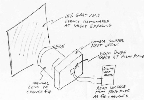
I took the photodiode and mounted
it at the film plane of an old manual exposure camera an old lens would
also work fine. I pointed the camera at an evenly illuminated 18%
gray card and adjusted the light so that the illumination was f5.6 at 1/50th
sec with 100 speed film. I then took readings of the voltage from
the photodiode as the lens was changed from f22 to f3.2 and made a graph
of the results. It is important to illuminate the 18% gray card with
the same or similar light source as your microscope will use. I used
a 3400 K tungsten source, the same color temperature as my fiber optic
microscope illuminator. The lens in this part becomes the standard
- the better the lens the better the results. If you can find a lens
with T stop markings than the results will be slightly better. T
stops are similar to f-stops, but represent the real light change due to
an aperture change and not the calculated change as a f-stop does.
I like to use the Microsoft product Excel as a graphing spreadsheet.
Once I have entered my data I can select the data
I want to graph and also create a trendline with an equation.

Once I know how my data fits
with a trend line, I can use the equation generated to extrapolate to other
f-numbers in between my data points.
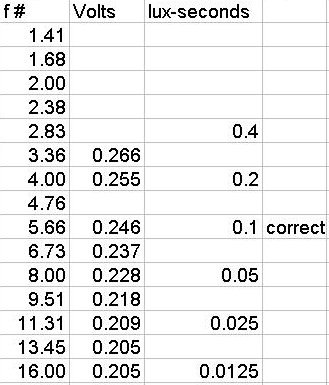
From this data we know the
correct exposure and can change it according to the change in film speed
or shutter speed.
To
calculate a correct exposure for 100 ASA film the equation
IT = C/S
can be used where
I = Lux, a unit of light intensity
C = a constant of 10 when
using Lux
T = Time in seconds
S = ASA film speed
Thus 100 ASA film requires
0.1 Lux-seconds to be correctly exposed.
As a side note if you have never
calculated f-numbers then there is an interesting relationship. The f-stop
or f-number is defined by the equation
f-stop = (sqrt 2) ^n
Where n is a whole integer
1, 2, 3, etc.
With all these relationships in hand,
the calculations becomes quite easy. Once again I use the program
Excel to do the calculations and display the results in a spreadsheet form
Below is my finished calibration
for the Lab Notebook, of course your results will depend on your selection
of photodiodes.
Before filming I like to verify the
calculations with a black and white film test. This turns out to
be a success as shown below. In this case I used a fixed slide of
mixed diatoms. The diatoms are very good for testing the resolution
of the system.
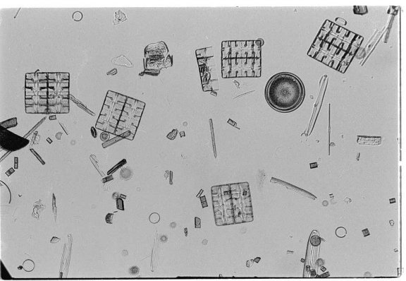
A 35 mm negative scanned
Onward to a color negative film test.
The purpose of this test is to check the color balance of the light source
and to really nail down the exposure. Since this test is done on
color reversal (slide film) the exposure latitude is quite tight.
Here you can see the test is also a success, but I would have been better
off to use an un-stained plant stem for the test. This stem is both
dyed green and red and the finished film is quite like the slide with an
over-all green cast.
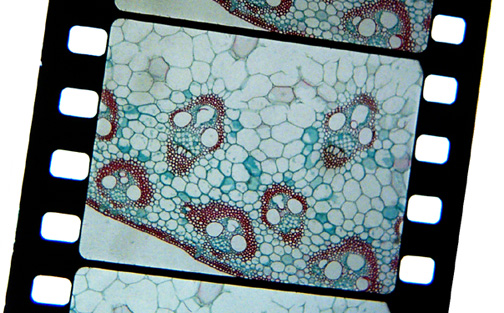
A digital picture of the resulting
film strip, taken
with a Kodak DC290 with a macro
lens
Conclusion
As you can see by the whole
process, it is not very difficult nor is it excessively time consuming.
For whatever photodiode you come by, the process must be repeated.
Build your own meter and start taking those amazing photos!
By-the-way if you are wondering
why I am filming using a motion picture camera? In motion picture
work, the camera films 24 frames a second where each frame has the digital
equivalent an 18-megabyte file as you can calculate - this represents an
incredible amount of data each second. Film still seems to be the
data collection medium of choice, at least for a few years yet.
If you have questions or comments
about this article , please do not hesitate to contact me,
Ted
Kinsman, home pages at www.sciencephotography.com
.
Reference Texts.
Camera Technology (The Dark Side
of the Lens)
Norman Goldberg
Acedemic Press, Inc. 1992
ISBN 0-12-287579-2
Photography Through The Microscope
The Kodak workshop Series
1988
John Gustav Delly
Kodak Series # E1528371
ISBN 0-87985-362-X
© Microscopy UK or their contributors.
Published in the December 2000
edition of Micscape Magazine.
Please report any Web problems or
offer general comments to the Micscape
Editor,
via the contact on current Micscape
Index.
Micscape is the on-line monthly magazine
of the Microscopy UK web
site at Microscopy-UK
WIDTH=1